Installation
Remove the operation panel right cover [A].
Thread the USB cable [B] through the notch in the front upper cover [A] and attach the ferrite core [C].

Reattach the front upper cover to the main machine.
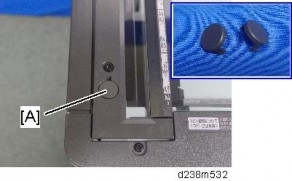
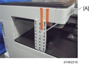
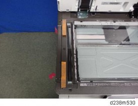
Attach the reader spacer [A].

Attach the sponge cushions [A] to the reader spacer.

Connect the card reader and interface cable.
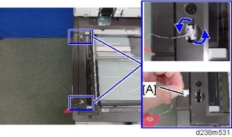
Make sure to turn the USB cable as shown so that it threads through the notch in the spacer [A].

Attach the reader cover [A].

Connect the USB cable to the main machine’s operation panel connector.

Installation
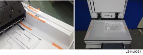
Thread the USB cable through the U-shaped groove [A] at the hinge of the operation panel and notch [B] in the cover under the cover.

Apply the clamp to fasten the USB cable to the main machine.
Make sure that the cable is not loose between the connector and hinge [A] and the hinge and clamp [B].

Tuck in the excess length portion of the USB cable in the space under the scanner.

Reattach the removed covers.
Installation

[A]: SD card slot 1 (option slot) [B]: SD card slot 2 (service slot)
Optional SD cards can be set in either slot 1 or slot 2. But slot 2 is the service slot, so we recommend that you use slot 1 to install the SD card options.
SD card options for this machine
OCR Unit Type M13 (page 2-262)
XPS Direct Print Option Type M19 (page 2-260)
PostScript3 Unit Type M19 (page 2-256)
Camera Direct Print Card Type M19 (page 2-258)
DataOverwriteSecurity Unit Type M19 (page 2-265)
SD Card for Fonts Type D
Unicode Font Package for SAP(R) 1 License
Unicode Font Package for SAP(R) 10 Licenses
Unicode Font Package for SAP(R) 100 Licenses
Fax Connection Unit Type M19
In this machine, it is possible to transfer data from a "Postscript3 Unit" SD card, unlike in earlier models, due to a change in the software licensing (the part of the Postscript software that requires licensing is now built into the controller, so the portion on the SD card can be moved to another SD card).
Since there are only two SD card slots (one of them is a service slot), three or more SD card applications cannot be used simultaneously.
However, if multiple SD card applications are merged, three or more SD card options can be used.
This function is referred to as the "SD card merge function".
The "SD card merge function" is a function which enables the use of three or more functions within the capacity of two SD cards by physically transferring the function of one SD card to other SD cards (all SD card options can be stored in two SD cards).
However, SD card applications are under license, therefore, since an SD card license after merge is transferred to the target SD card, it cannot be used even if it is moved to the target machine.
Also, a process to prevent illegal copying is performed.
After merge, store the empty SD card in the location shown below.
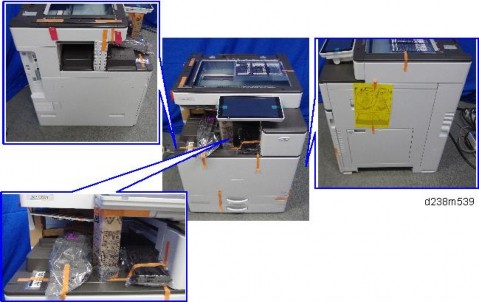
Open the right door, and then remove the small cover [A].

Remove the screw and the connector, and then remove the front upper cover [A].

Remember that there is a tab at the positions in the red arrows.
Rotate the operation panel [B] upward to a horizontal position, and then detach the
Installation
front upper cover [A].

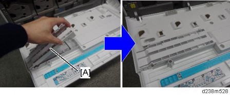
Insert the SD card in the storage location [A] inside the cover.

"Move Exec" (SP5-873-001) lets you move application programs from the original SD card to another SD card.
The SD card as a destination is not specified.
Turn the OFF the main power.
Remove the SD card slot cover [A] ![]() ×1).
×1).

Set the destination SD card (SD card where data is to be stored) in Slot 1 [A], and set the original SD card (SD card from which data is to be transferred) in Slot 2 [B].

Turn ON the main power, and press [ENTER] in SP5-873-001 (SD Card Appli Move: Move Exec).
When a confirmation screen is displayed, press [ENTER] (it takes about 2 - 3 minutes).
If [CANCEL] is pressed, the display returns to the previous screen.
Note that if the power supply is turned off, a panel operation is performed, or the cover is opened during merge, it will result in a malfunction.
When merge is complete, and the following screen is displayed, press [CLOSE].
If the process is terminated abnormally, perform the merge in SP mode again.
If the capacity of the destination SD card is insufficient, the merge operation cannot be performed.
Press [END] twice.
Turn OFF the main power.
Remove the empty SD card after transfer from Slot 2.
Reattach the slot cover ![]() ×1).
×1).
Turn ON the main power, output the system setting list, and check that the options are recognized correctly.
"Undo Exec" (SP5-873-002) lets you move back application programs from an SD card in Slot 1 (upper) to the original SD card in Slot 2 (lower). You can use this program when, for example, you have mistakenly copied some programs by using “Move Exec”.
Turn OFF the main power.
Remove the SD card slot cover [A] ![]() ×1).
×1).

Installation
Insert the integrated SD card in Slot 1 [A: Upper].

Insert the SD card which became empty after integration in Slot 2 (lower slot).
Turn On the main power, and press [ENTER] in SP5-873-002 (SD Card Appli Move: Undo Exec).
When a confirmation screen is displayed, press [ENTER].
If [CANCEL] is pressed, the display returns to the previous screen.
Note that if the power supply is turned off, a panel operation is performed, or the cover is opened during cancellation, it will result in a malfunction.
When cancellation is complete, press [CLOSE].
Press [END] twice.
Turn OFF the main power.
Reattach the SD card slot cover ![]() ×1).
×1).
Turn ON the main power, and check that the application has been deleted.
No. | Description | Q’ty |
1 | SD Card | 1 |
2 | PS3 Decal | 1 |

When installing more than one SD card, perform the merge operation (page 2-252 "SD Card Appli Move").
Remove the SD card slot cover [A].

Insert the PS3 SD card in SD card slot 1 [A: Upper Slot].

Installation
Reattach the SD card slot cover ![]() ×1).
×1).
Stick the "Adobe PostScript3" decal [A] on the front face of the MFP.

Turn ON the main power.
Print out the "Configuration Page", and then check if this option is correctly recognized.
User Tools > Machine Features > Printer Features > List/Test Page > Configuration Page
The PDF firmware installed as standard contains a program required to print PS3 data as default. However, this PS3 program is normally disabled.
The PS3 firmware is a dongle (key) which enables PS3 data printing functions. When the PS3 firmware is installed, the PS3 program in the PDF firmware is enabled. Due to this specification, the self-diagnosis result report shows the ROM part number/software version of the PDF firmware contained in the PS3 program.
No. | Description | Q’ty |
1 | SD Card | 1 |
When installing more than one SD card, perform the merge operation (page 2-252 "SD Card Appli Move").
Remove the SD card slot cover [A].

Insert the Camera Direct Print Card in SD card slot 1 [A: Upper Slot].

Installation
Reattach the SD card slot ![]() ×1)
×1)
Turn ON the main power.
Attach the "PictBridge" decal on the front face of the MFP.
Print out the "Configuration Page", and then check if this option is correctly recognized.
User Tools > Machine Features > Printer Features > List/Test Page > Configuration Page
No. | Description | Qty | Remarks |
1 | XPS Direct Print SD Card | 1 |
When installing more than one SD card, perform the merge operation (page 2-252 "SD Card Appli Move").
Remove the SD card slot cover [A].

Insert the XPS SD card in SD card slot 1 [A: Upper Slot].

Installation
Reattach the SD card slot cover ![]() ×1).
×1).
Turn ON the main power.
Print out the "Configuration Page", and then check if this option is correctly recognized.
User Tools > Machine Features > Printer Features > List/Test Page > Configuration Page
No. | Description | Q’ty |
1 | SD Card | 1 |
This option adds a searchable PDF function to the scanning function.
The searchable PDF function performs OCR by the MFP on a document read with the scanner, and embeds text data in the PDF. This permits PDF text browsing, automatic assignment of filenames, and automatic alignment of document orientation.
This option is provided with an SD card. By installing an SD card in the MFP, a functional icon is added to the control unit. It is not necessary to install software in a PC.
If this option is installed, various settings related to the searchable PDF function are available.
After reading of the document is completed (after it is read by the SPDF/ARDF and output), OCR is performed. Therefore, after reading is completed, documents can be collected from the document glass or SPDF/ARDF.
Other functions, such as the copy function and printer function, can be used during OCR.
When installing more than one SD card, perform the merge operation (page 2-252 "SD Card Appli Move").
Remove the SD card slot cover [A].

Installation
Insert the OCR Unit SD card in SD card slot 1 [A: Upper Slot].

Turn ON the main power.
Enter the SP mode, and then press "Enter" in SP5-878-004 (Option Setup: OCR Dictionary).
The SD card ID is saved in the NVRAM, and the ID of the MFP is saved on the SD card. The MFP and SD card are thereby linked.
When "operation complete" is displayed, press "Close".
If installation fails, "Failed" is displayed.
If installation fails, perform the following steps.
Check whether it is a used SD card.
Switch the power OFF, and repeat steps 1-5.
Turn the machine OFF and back ON again.
Press "Enter" in SP5-878-004 (Option Setup: OCR Dictionary).
Dictionary data is copied to the HDD.
On the first run, SP5-878-004 links the SD card, and on the second run, copies dictionary data.
Turn OFF the main power.
Remove the SD card from the SD card slot.
Keep the SD card in the SD card storage location of the MFP. The original SD card is needed in the event of a HDD malfunction.
Reattach the SD card slot cover.
Turn ON the main power.
Press [File Format / File Name] on the scanner function screen.
Check that [OCR setting] is displayed on the "File format / "File Name" screen.
After installation, the OCR setting can be changed on the "OCR setting" screen.
When setting OCR, set [OCR setting] to [Yes]. (Default setting: [No])
When this option is installed, a function is saved on the HDD, and ID information on the SD card is saved in the NVRAM. Therefore, when replacing the HDD and NVRAM, this option must be reinstalled.
When storing the original SD card
When only the HDD is replaced Reinstall using the original SD card.
When only the NVRAM is replaced
When performing upload/download of NVRAM data, reinstall using the original SD card. When not performing upload/download of NVRAM data, order and reinstall a new SD card (service part).
When the HDD and NVRAM are replaced simultaneously Reinstall using the original SD card.
If the original SD card is lost
Order and reinstall a new SD card (service part).
Installation
The machine’s hard disk stores all document data from the Copier, Printer, and Scanner functions. It also stores the data of users’ Document Server and code counters, and the Address Book. To prevent data on the hard disk being leaked before disposing of the machine, you can overwrite all data stored on the hard disk (Erase All Memory). You can also automatically overwrite temporarily-stored data (Auto Erase Memory).
The function of this option is completely the same as the Data Overwrite Security in Security Functions, which is standard on this machine (page 2-278 "Security Settings")
This option should be installed only for the customer who requires the CC certified Data Overwrite Security function.
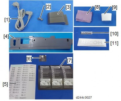
Check the quantity and condition of the accessories in the box against the following list.
No. | Description | Q’ty |
1 | SD Card | 1 |
- | Comments Sheet | 1 |
- | Operating Instructions CD-ROM | 1 |
Confirm that the Data Overwrite Security unit SD card is the correct type for the machine. The correct type for this machine is "Type M19".
If you install any version other than "Type M19" for this machine, you will have to replace the NVRAM and do this installation procedure again.
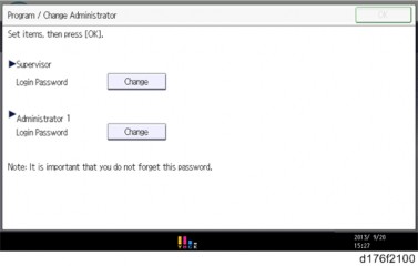
Make sure that the following settings are not at their factory default values:
Supervisor login password
Administrator login name
Administrator login password
If any of these settings is at a factory default value, tell the customer these settings must be changed before you do the installation procedure.
Make sure that "Admin. Authentication" is ON.
User Tools > Machine Features > System Settings > Administrator Tools > Administrator Authentication Management > Admin. Authentication
If this setting is OFF, tell the customer this setting must be ON before you do the installation procedure.
Make sure that "Administrator Tools" is enabled (selected).
User Tools > Machine Features > System Settings > Administrator Tools > Administrator Authentication Management> Available Settings
If this setting is disabled (not selected), tell the customer this setting must be enabled (selected) before you do the installation procedure.
See the Operating Instructions (Security Guide) for the factory default values.
Seal Check and Removal
Before opening the corrugated envelope, make sure that the seal has not been broken or peeled off. If the seal has been broken or peeled off (even partially), this is considered an arrival defect. Note that once the seal is peeled off, this will leave a mark on the bag.
Installation
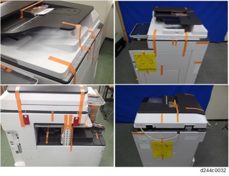
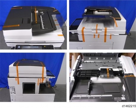
You must check the box seals to make sure that they were not removed after the items were sealed in the box at the factory before you do the installation.
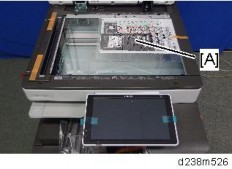
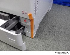
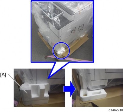
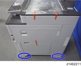
Check the box seals [A] on each corner of the box.
Make sure that a tape is attached to each corner.
The surfaces of the tapes must be blank. If you see "VOID" on the tapes, do not install the components in the box.
If the surfaces of the tapes do not show "VOID", remove them from the corners of the box.
You can see the "VOID" marks [B] when you remove each seal. In this condition, they cannot be attached to the box again.
Turn the main power off, and then remove the power plug and cables that are connected.
Remove the SD card slot cover [A].
Insert the DataOverwriteSecurity Unit Type M19 SD card in SD card slot 1 [A: Upper Slot].

Reattach the SD card slot cover ![]() ×1).
×1).
Insert the power cord into the outlet and turn ON the main power.
When installing more than one SD card, perform the merge operation.
Enter the SP mode.
Do this step only if you are installing the option on a machine that is already in use (not a new machine):
If the customer wishes to continue using the same hard disk, execute all three SP modes below.
SP5-801-014 (Clear DCS Setting)
SP5-832-001 (HDD Formatting (ALL))
SP5-832-002 (HDD Formatting (IMH))
If customer wishes to replace the hard disk with a new one, execute SP5-801-014 only.
If the customer continues using the same hard disk, the overwriting of the data stored on the disk before the option is installed cannot be guaranteed. It is highly recommended to replace the hard disk with a new one.
Set SP5-836-001 (Capture Function (0:Off 1:On)) to a value of 0 (disable).
Execute SP5-878-001 ([Option Setup: Data Overwrite Security)
If the installation fails, "Installation failed" is displayed when this SP is executed.
Print out the System Settings List and make sure that the option was installed successfully.
Reconnect the network cable.
Execute SP5-990-005 (SP print mode Diagnostic Report).
Make sure to shut down and reboot the machine once before printing the SMC. Otherwise, the latest settings may not be collected when the SMC is printed.
Make sure that ROM number "D3BC5757A" and firmware version "1.02" appear in both of the following areas on the report (they must match):
"ROM Number / Firmware Version" - "HDD Format Option"
"Loading Program"
Installation
Press the [User Tools] icon.
Press [Machine Features].
Press [System Settings].
Press [Administrator Tools].
Press [Next] three times.
Press [Auto Erase Memory Setting].
Press [On].
Select the method of overwriting.
If you select [NSA] or [DoD], proceed to Step 11.
If you select [Random Numbers], proceed to Step 9.
Press [Change].

Enter the number of times that you want to overwrite using the ten keys, and then press [#].
The Random Numbers method overwrites the data using random numbers. You can set the overwrite to be performed anywhere from 1-9 times, with a default of 3 times.
Press [OK].
Make sure that the Data Overwrite icon is displayed in the bottom right hand corner of the screen.
Take a test copy, and then make sure that the Data Overwrite icon changes from "Dirty" (solid) to "Dirty" (blinking), and then to "Clear".
If the Data Overwrite icon does not change to Clear, check to see if there are any active Sample Print or Locked Print jobs. A Sample Print or Locked Print job can only be overwritten after it has been executed.
The Dirty icon blinks while an overwrite is in progress.
If you use your machine for a while with Auto Erase Memory disabled, and then suddenly enable it, the overwrite process may take 10 or more hours depending on HDD usage.
Data Overwrite icon:
| Icon [1] | This icon is lit when there is temporary data to be overwritten, and blinks during overwriting. |
| Icon [2] | This icon is lit when there is no temporary data to be overwritten. |
SP descriptions
SP5-801-014 (Memory Clear: Clear DCS Setting) Initializes the DCS (Delivery Control Service) settings.
SP5-832-001 (HDD Formatting : HDD Formatting (ALL)) Initializes the hard disk.
SP5-832-002 (HDD Formatting : HDD Formatting (IMH)) Initializes the hard disk.
SP5-836-001 (Capture Settings: Capture Function (0:Off 1:On))
With this function disabled, the settings related to the capture feature cannot be initialized, displayed, or selected.
5-878-001 (Data Overwrite Security)
Enables the Data Overwrite Security unit. Press "EXECUTE" on the operation panel. Then turn the machine off and on.
Installation
SP5-990-005 (SP Print Mode: Diagnostic Report).
Prints the configuration sheets of the system and user settings : SMC.
Make sure to shut down and reboot the machine once before printing the SMC. Otherwise, the latest settings may not be collected when the SMC is printed.
Prepare and check the following check points before you visit the customer site. For details, ask the @Remote key person.
Check points before making @Remote settings
The setting of SP5-816-201 in the mainframe must be "0".
Print the SMC with SP5-990-002 and then check if a device ID2 (SP5-811-003) must be correctly programmed.
6 spaces must be put between the 3-digit prefix and the following 8-digit number (e.g. xxx _xxxxxxxx).
ID2 (SP5-811-003) and the serial number (SP5-811-001) must be the same (e.g. ID2: A01 _23456789 = serial No. A0123456789)
Make sure to shut down and reboot the machine once before printing the SMC. Otherwise, the latest settings may not be collected when the SMC is printed.
The following settings must be correctly programmed.
Proxy server IP address (SP5-816-063)
Proxy server Port number (SP5-816-064)
Proxy User ID (SP5-816-065)
Proxy Password (SP5-816-066)
Get a Request Number Execute the @Remote Settings
Enter the SP mode.
Input the Request number which you have obtained from @Remote Center GUI, and then enter [OK] with SP5-816-202.
Confirm the Request number, and then click [EXECUTE] with SP5-816-203.
Check the confirmation result with SP5-816-204.
Value | Meaning | Solution/ Workaround |
0 | Succeeded | - |
3 | Communication error (proxy enabled) | Check the network condition. |
4 | Communication error (proxy disabled) | Check the network condition. |
5 | Proxy error (authentication error) | Check Proxy user name and password. |
Value | Meaning | Solution/ Workaround |
6 | Communication error | Check the network condition. |
8 | Other error | See "SP5816-208 Error Codes" below this. |
9 | Request number confirmation executing | Processing… Please wait. |
11 | Already registered | - |
12 | Parameter error | - |
20 | Dial-up authentication error | * These errors occur only in the modems that support @Remote. |
21 | Answer tone detection error | |
22 | Carrier detection error | |
23 | Invalid setting value (modem) | |
24 | Low power supply current | |
25 | unplugged modem | |
26 | Busy line |
Installation
Make sure that the screen displays the Location Information with SP5-816-205 only when it has been input at the Center GUI.
Click [EXECUTE] to execute the registration with SP5-816-206.
Check the registration result with SP5-816-207.
Value | Meaning | Solution/ Workaround |
0 | Succeeded | - |
1 | Request number error | Check the request number again. |
2 | Already registered | Check the registration status. |
3 | Communication error (proxy enabled) | Check the network condition. |
4 | Communication error (proxy disabled) | Check the network condition. |
Value | Meaning | Solution/ Workaround |
5 | Proxy error (Authentication error) | Check Proxy user name and password. |
8 | Other error | See "SP5-816-208 Error Codes" below this. |
9 | Request number confirmation executing | Processing… Please wait. |
11 | Already registered | - |
12 | Parameter error | - |
20 | Dial-up authentication error | * These errors occur only in the modems that support @Remote. |
21 | Answer tone detection error | |
22 | Carrier detection error | |
23 | Invalid setting value (modem) | |
24 | Low power supply current | |
25 | unplugged modem | |
26 | Busy line |
Exit the SP mode. SP5-816-208 Error Codes
Caused by Operation Error, Incorrect Setting
Code | Meaning | Solution/ Workaround |
-12002 | Inquiry, registration attempted without acquiring Request No. | Obtain a Request Number before attempting the Inquiry or Registration. |
-12003 | Attempted registration without execution of a confirmation and no previous registration. | Perform Confirmation before attempting the Registration. |
-12004 | Attempted setting with illegal entries for certification and ID2. | Check ID2 of the mainframe. |
Code | Meaning | Solution/ Workaround |
-12005 | @Remote communication is prohibited. The device has an Embedded RC gate-related problem. | Make sure that "Remote Service" in User Tools is set to "Do not prohibit". |
-12006 | A confirmation request was made after the confirmation had been already completed. | Execute registration. |
-12007 | The request number used at registration was different from the one used at confirmation. | Check Request No. |
-12008 | Update certification failed because mainframe was in use. | Check the mainframe condition. If the mainframe is in use, try again later. |
-12009 | The ID2 in the NVRAM does not match the ID2 in the individual certification. | Check ID2 of the mainframe. |
-12010 | The certification area is not initialized. | Initialize the certification area. |
Installation
Error Caused by Response from GW URL
Code | Meaning | Solution/ Workaround |
-2385 | Other error | |
-2387 | Not supported at the Service Center | |
-2389 | Database out of service | |
-2390 | Program out of service | |
-2391 | Two registrations for the same mainframe | Check the registration condition of the mainframe |
-2392 | Parameter error | |
-2393 | External RCG not managed | |
-2394 | Mainframe not managed | |
-2395 | Box ID for external RCG is illegal. |
Code | Meaning | Solution/ Workaround |
-2396 | Mainframe ID for external RCG is illegal. | |
-2397 | Incorrect ID2 format | Check the ID2 of the mainframe. |
-2398 | Incorrect request number format | Check the Request No. |
SP descriptions
SP5-816-201 (Remote Service: Regist Status DFU(SSP))
Displays a number that indicates the status of the @Remote service device.
0: Neither the registered device by the external nor embedded RCG device is set.
1: The embedded RCG device is being set. Only Box registration is completed. In this status, this unit cannot answer a polling request from the external RCG.
2: The embedded RCG device is set. In this status, the external RCG unit cannot answer a polling request.
3: The registered device by the external RCG is being set. In this status the embedded RCG device cannot be set.
4: The registered module by the external RCG has not started.
SP5-990-002 (SP Print Mode: SP(Mode Data List))
Prints the configuration sheets of the system and user settings : SMC.
Make sure to shut down and reboot the machine once before printing the SMC. Otherwise, the latest settings may not be collected when the SMC is printed.
SP5-811-003 (Machine No. Setting: ID2 Code Display)
Sets the ID-2 code used to identify the @remote device at installation.
SP5-816-063 (Remote Service: Proxy server IP address)
This SP sets the address of the proxy server used for communication between the RCG device and the gateway. Use this SP to set up or display the customer proxy server address. The address is necessary to set up the embedded RCG-N.
The address display is limited to 127 characters. Characters beyond the 127 characters are ignored.
This address is customer information and is not printed in the SMC report.
SP5-816-064 (Remote Service: Proxy server Port number)
This SP sets the port number of the proxy server used for communication between the embedded RCG-N and the gateway. This setting is necessary to set up the embedded RC Gate-N.
This port number is customer information and is not printed in the SMC report.
SP5-816-065 (Remote Service: Proxy User ID)
This SP sets the HTTP proxy certification user name.
Installation
The length of the name is limited to 31 characters. Any character beyond the 31st character is ignored.
This name is customer information and is not printed in the SMC report.
SP5-816-066 (Remote Service: Proxy Password)
This SP sets the HTTP proxy certification password.
The length of the password is limited to 31 characters. Any character beyond the 31st character is ignored.
This name is customer information and is not printed in the SMC report.
SP5-816-202 (Remote Service: Letter Number DFU(SSP))
Allows entry of the number of the request needed for the RCG-N device.
SP5-816-203 (Remote Service: Confirm Execute)
Executes the inquiry request to the @Remote GW URL.
SP5-816-204 (Remote Service: Confirm Result DFU(SSP))
Displays a number that indicates the result of the inquiry executed with SP5816 203.
SP5-816-205 (Remote Service: Confirm Place DFU(SSP))
Displays the installed section informed from G/W for response of request number inquiry if the section is enrolled on the G/W.
SP5-816-206 (Remote Service: Register Execute)
Executes "Embedded RCG Registration".
SP5-816-207 (Remote Service: Register Result DFU(SSP)
Displays a number that indicates the registration result.
The machine contains the Security functions (Data Overwrite Security and HDD Encryption unit) in the controller board.
If you are installing a new machine, it is recommended to activate the Data Overwrite Security and HDD Encryption by selecting "Format All Data" from "System Settings" on the operation panel.
This method is recommended because there is no user data on the hard drive yet (Address Book data, image data, etc.).
If the customer wishes to activate the Data Overwrite Security and HDD Encryption unit on a machine that is already running, it is recommended to activate the unit by selecting "All Data" from "System Settings" on the operation panel.
Selecting "All Data" will preserve the data that has already been saved to the HDD. (If "Format All Data" is selected, all user data saved to the HDD up to that point will be erased).
Immediately after encryption is enabled, the encryption setting process will take several minutes to complete before you can begin using the machine.
If encryption is enabled after data has been stored on the HDD, or of the encryption key is changed, this process can take up to three and a half hours or more.
The machine cannot be operated while data is being encrypted. Once the encryption process begins, it cannot be stopped.
Make sure that the machine's main power is not turned off while the encryption process is in progress.
If the machine's main power is turned off while the encryption process is in progress, the HDD will be damaged and all data on it will be unusable.
Print the encryption key and keep the encryption key (which is printed as a paper sheet).
Keep the encryption key in a safe place. If the encryption key is lost and is needed, the controller board, HDD and NVRAM must all be replaced at the same time.
"NVRAM" mentioned in here means the NVRAM on the Controller Board.
"NVRAM" or EEPROM on the BCU has nothing to do with this.
Please use the following procedure when the Data Overwrite Security and HDD Encryption are reinstalled.
Installation
Before You Begin the Procedure
Make sure that the following settings (1) to (3) are not at their factory default values.
Supervisor login password
Administrator login name
Administrator login password
If any of these settings is at a factory default value, tell the customer these settings must be changed before you do the installation procedure.
Make sure that "Admin. Authentication" is on.
[User Tools] icon -> [Machine Features] -> [System Settings] -> [Administrator Tools] -> [Administrator Authentication Management] -> [Admin. Authentication]
If this setting is off, tell the customer this setting must be on before you do the installation procedure.
Make sure that "Administrator Tools" is enabled (selected).
[User Tools] icon -> [Machine Features] -> [System Settings] -> [Administrator Tools] -> [Administrator Authentication Management] -> [Available Settings]
If this setting is disabled (not selected), tell the customer this setting must be enabled (selected) before you do the installation procedure.
Installation Procedure
Connect the network cable if it needs to be connected.
Turn ON the main power.
Go into the SP mode and push "EXECUTE" in SP5-878-001.
Exit the SP mode and turn off the operation switch. Then turn off the main power switch.
Turn on the machine power.
Do SP5-990-005 (SP print mode Diagnostic Report).
Make sure to shut down and reboot the machine once before printing the SMC. Otherwise, the latest settings may not be collected when the SMC is printed.
Go into the User Tools mode, and select [Machine Features] ![]() [System Settings]
[System Settings] ![]() [Administrator Tools]
[Administrator Tools] ![]() [Auto Erase Memory Setting]
[Auto Erase Memory Setting] ![]() [On].
[On].
Exit the User Tools mode.
| Icon [1] | This icon is lit when there is temporary data to be overwritten, and blinks during overwriting. |
| Icon [2] | This icon is lit when there is no temporary data to be overwritten. |
Check the display and make sure that the overwrite erase icon appears.
Check the overwrite erase icon.
The icon [1] is lit when there is temporary data to be overwritten, and blinks during overwriting.
The icon [2] is lit when there is no temporary data to be overwritten.
Using Auto Erase Memory
The Auto Erase Memory function can be enabled by the following procedure.
Log in as the machine administrator from the control panel.
Press the [User Tools] icon.
Press [Machine Features].
Press [System Settings].
Press [Administrator Tools].
Press [Next] three times.
Press [Auto Erase Memory Setting].
Installation
Press [On].
Select the method of overwriting.
If you select [NSA] or [DoD], proceed to step 12.
If you select [Random Numbers], proceed to step 10.
Press [Change].
Enter the number of times that you want to overwrite using the number keys, and then press [#].
Press [OK]. Auto Erase Memory is set.
Log out.
Check the display and make sure that the overwrite erase icon appears.
Check the overwrite erase icon.
The icon [1] is lit when there is temporary data to be overwritten, and blinks during overwriting.
The icon [2] is lit when there is no temporary data to be overwritten.

| Icon [1] | This icon is lit when there is temporary data to be overwritten, and blinks during overwriting. |
| Icon [2] | This icon is lit when there is no temporary data to be overwritten. |
Before You Begin the Procedure:
Make sure that the following settings (1) to (3) are not at the factory default settings.
Supervisor login password
Administrator login name
Administrator login password
If any of these settings is at a factory default value, tell the customer these settings must be changed before you do the installation procedure.
Confirm that "Admin. Authentication" is on:
[User Tools] icon - [Machine Features] - [System Settings] - [Administrator Tools] - [Administrator Authentication Management] - [Admin. Authentication] - [On]
If this setting is off, tell the customer that this setting must be on before you can do the installation procedure.
Confirm that "Administrator Tools" is selected and enabled.
[User Tools] icon - [Machine Features] - [System Settings] - [Administrator Tools] - [Administrator Authentication Management] - [Available Settings]
"Available Settings" is not displayed until step 2 is done.
If this setting is not selected, tell the customer that this setting must be selected before you can do the installation procedure.
Installation Procedure:
Turn ON the main power, and then enter the SP mode.
Select SP5-878-002, and then press "Execute" on the LCD.
Exit the SP mode after "Completed" is displayed on the LCD.
Turn OFF the main power.
Installation
Enable Encryption Setting
Machine Data Encryption Settings can be enabled by the following procedure.
When setting up encryption, specify whether to start encryption after deleting data (initialize) or encrypt and retain existing data. If data is retained, it may take some time to encrypt it.
Turn ON the main power.
Log in as the machine administrator from the control panel.
Press the [User Tools] icon.
Press [Machine Features].
Press [System Settings].
Press [Administrator Tools].
Press [Next] three times.
Press [Machine Data Encryption Settings].
Press [Encrypt].
Select the data to be carried over to the HDD and not be reset.
To carry all of the data over to the HDD, select [All Data].
To carry over only the machine settings data, select [File System Data Only].
To reset all of the data, select [Format All Data].
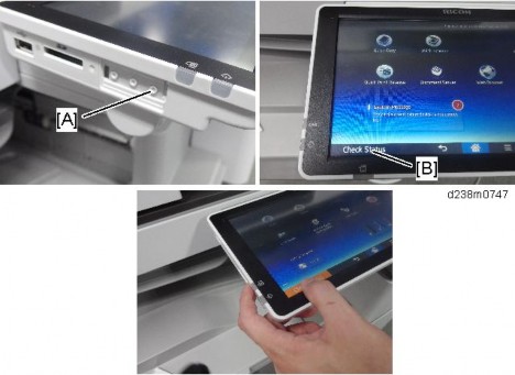
Select the backup method.
If you have selected [Save to SD Card], load an SD card into the media slot on the side of the control panel and press [OK] to back up the machine's data encryption key.
If you have selected [Print on Paper], press the [Start] key. Print out the machine's data encryption key.
Press [OK].
Press [Exit].
Press [Exit].
Installation
Log out.
Turn OFF the main power, and then turn the main power back ON.
The machine will start to convert the data on the memory after you turn on the machine. Wait until the message "Memory conversion complete. Turn the main power switch off." appears, and then turn the main power off again.
Check the Encryption Settings
Press the [User Tools] icon.
Press [Machine Features].
Press [System Settings].
Press [Administrator Tools].
Press [Machine Data Encryption Settings].
Confirm whether the encryption has been completed or not on this display.
Print the encryption key
Use the following procedure to print the key again if it has been lost or misplaced.
Press the [User Tools] icon.
Press [Machine Features].
Press [System Settings].
Press [Administrator Tools].
Press [Machine Data Encryption Settings].
If this item is not visible, press [Next] to display more settings.
Press [Print Encryption Key].
Encryption key sample
The encryption key is printed out as a sheet of paper like the example shown above. Please instruct the customer to keep it in a safe place.
Backing Up the Encryption Key
The encryption key can be backed up. Select whether to save it to an SD card or to print it.
The encryption key is required for data recovery if the machine malfunctions. Be sure to store the encryption key safely for retrieving backup data.
Log in as the machine administrator from the control panel.
Press the [User Tools] icon.
Press [Machine Features].
Press [System Settings].
Press [Administrator Tools].
Press [Next] three times.
Press [Machine Data Encryption Settings].
Press [Print Encryption Key].

Installation
Select the backup method.
If you have selected [Save to SD Card], load an SD card into the media slot on the side of the control panel and press [OK]; once the machine's data encryption key is backed up, press [Exit].
If you have selected [Print on Paper], press the [Start] key. Print out the machine's data encryption key.
Press [Exit].
Log out.
Encryption Key Restoration
How to restore the old encryption key to the machine
The following message appears after the controller board is replaced. In such a case, it is necessary to restore the encryption key to the new controller board.

To do this, follow the procedure below.
Prepare an SD card that has been initialized in FAT16 format.
Using a PC, create a folder in the SD card and name it "restore_key".
Create a folder in the "restore_key" folder and name it the same as machine’s serial number, "xxxxxxxxxxx" (11 digits).
Create a text file called "key_xxxxxxxxxxx.txt" and save it in the "xxxxxxxxxxx" folder. Write the encryption key in the text file.
/restore_key/xxxxxxxxxxx/key_xxxxxxxxxxx.txt
Ask an Administrator to enter the encryption key. The key has already been printed out by the user and may have been saved in the "key_xxxxxxxxxxx.txt" file. (The function of back-up the encryption key to the SD card directly is provided 11A
products or later.)
Turn ON the machine’s main power.
Confirm that a message is displayed on the LCD telling to insert the SD card that contains the encryption key.
Turn OFF the main power.
Insert the SD card that contains the encryption key into SD card slot 2 (the lower slot).
Turn ON the main power.
The machine will automatically restore the encryption key to the flash memory on the controller board.
Turn OFF the main power when the machine has returned to normal status.
Remove the SD card from SD card slot 2.
How to do a forced start up with no encryption key
If the encryption key back-up has been lost, follow the procedure below to do a forced start-up.
The HDD will be formatted after the forced start-up.
Encrypted data will be deleted.
User settings will be cleared.
Prepare an SD card.
Create a directory named "restore_key" inside the root directory of the SD card. Then, save the "nvram_key.txt" file using the following name:
/restore_key/nvram_key.txt
Create a text file and write "nvclear".
Write this string at the head of the file.
Use all lower-case letters.
Do not use quotation marks or blank spaces.
It is judged that a forced start has been selected when the content of "nvclear" is executed and the machine shifts to the alternate system (forced start).
Confirm that a message is displayed on the LCD telling to insert the SD card that contains the encryption key.
Turn off the main power.
Insert the SD card that contains the encryption key into SD card slot 2 (the lower slot).
Turn ON the main power.
The machine automatically clear the HDD encryption.
Turn OFF the main power when the machine has returned to normal status.
Remove the SD card from SD card Slot 2.
Turn ON the main power.
Installation
Memory clear SP5-801-xxx (Exclude SP-5-801-001: All Clear and SP-5-801-002: Engine), and clear SP5-846-046: address book.
Set necessary user settings in User Tools.
SP descriptions
SP5-878-002 (Option Setup: HDD Encryption)
Executes the setup for encryption.
SP5-990-005 (SP Print Mode: Diagnostic Report)
Prints the configuration sheets of the system and user settings : SMC.
Make sure to shut down and reboot the machine once before printing the SMC. Otherwise, the latest settings may not be collected when the SMC is printed.
SP5-801-001 (Memory Clear: All Clear)
Resets all correction data for process control and all software counters, and returns all modes and adjustments to their default values.
SP5-801-002 (Memory Clear: Engine)
Clears non-volatile memory of engine.
SP5-846-046 (UCS Setting: Addr Book Media)
Displays the slot number where an address book data is in. 0: Unconfirmed
1: SD Slot 1
2: SD Slot 2
3: SD Slot 3
4: USB Flash ROM 10: SD Slot 10
20: HDD
30: Nothing
Installation
RE V IS ION H IST ORY | ||
Page | Date | Added/ Updated/ New |
None | ||
Preventive Maintenance
There are two ways to reset the PM counter for this machine.
"Method 2 By [PM Counter / New Unit Set] Menu" is recommended for its ease of operation.
After the PM counter for the fusing sleeve belt unit reaches its PM life (400K pages or 313,153,000 mm), the machine stops the operation automatically. Replace the fusing sleeve belt unit before the machine stops its operation (stop warning: 415K pages or 302,229,000 mm, stop: 430K pages or 313,153,000 mm).
For the following units, there is a new unit detection mechanism. It is not necessary to set SPs (New Unit Detection).
Fusing unit as a complete unit
PCDU as a complete unit
Waste Toner Bottle (When the machine stopped because the waste toner bottle was full)
Method 1: By SP3701
Enter the SP mode.
Output the SMC logging data with SP5-990-004.
Make sure to shut down and reboot the machine once before printing the SMC. Otherwise, the latest settings may not be collected when the SMC is printed.
Set the following SPs (New Unit Detection) to "1".
Item | SP |
Black: SP3-701-003 | |
Development unit | Yellow: SP3-701-072 |
Cyan: SP3-701-026 | |
Magenta: SP3-701-049 | |
Black: SP3-701-002 | |
PCU | Yellow: SP3-701-071 |
Cyan: SP3-701-025 | |
Magenta: SP3-701-048 |
Replacement procedure: page 4-61
Replacement procedure: page 4-61
Item | SP |
Pressure roller | Pressure roller: SP3-701-118 Fusing sleeve belt unit: SP3-701-116 |
Image Transfer Belt Unit | SP3-701-093 |
Image Transfer Cleaning Unit | SP3-701-102 |
Paper Transfer Roller Unit | SP3-701-109 |
Waste Toner Bottle (When the bottle is replaced before the machine detects bottle full and stops) | SP3-701-142 |
Ozone Filter, Dust Filter | SP3-701-131 |
Replacement procedure: page 4-137 Fusing sleeve belt unit
Replacement procedure: page 4-134 (Complete fusing unit is not necessary to set SP3-701.)
Replacement procedure: page 4-71
Replacement procedure: page 4-75
Replacement procedure: page 4-89
Replacement procedure: page 4-69
Replacement procedure: page 4-207
Turn the main power switch OFF, and disconnect the power cord from the outlet.
Replace the PM parts and turn the main power ON.
The machine will reset the PM counters automatically. In the case of the development unit, developer initialization will also be done automatically.
Exit the SP mode.
Method 2: By [PM Counter / New Unit Set] Menu
Enter the SP mode.
Output the SMC logging data with SP5-990-004.
Make sure to shut down and reboot the machine once before printing the SMC. Otherwise, the latest settings may not be collected when the SMC is printed.
Press [PM Counter / New Unit Set].

Preventive Maintenance
Press [All PM Parts List : New Unit Set].

Set the PM part that you want to replace to "YES" under "New Unit Set".
After pressing "YES", the [Exit] key will not be available.
Turn OFF the main power and unplug the power cord from the wall outlet.
Replace the PM parts and turn the main power ON.
The machine will reset the PM counters automatically. In the case of the development unit, developer initialization will also be done automatically.
Exit the SP mode.
Output the SMC logging data with SP5-990-004 and check the counter values.
Make sure to shut down and reboot the machine once before printing the SMC. Otherwise, the latest settings may not be collected when the SMC is printed.
Make sure that the PM counters for the replaced units are "0" with SP7-621, or SP7-944. If the PM counter for a unit was not reset, then execute the new unit detect setting with SP3-701 again and turn the machine OFF/ON.
Make sure that the exchange counter counts up with SP7-853.
Make sure that the counters for the previous units (SP7-908) on the new SMC logging data list (from step 2 above) are equal to the counters (SP7-621, or SP7-944) for these units on the previous SMC logging data list (the list that was output in the "Before removing the old parts" section).
Make sure that the unit replacement date is updated with SP7-950.
SP Descriptions
SP7-621-001 (PM Counter Display: Paper)
Displays the number of sheets printed for each current maintenance unit.
When a unit is replaced, the machine automatically detects that the new unit is installed. Then, the current PM counter value is automatically moved to the PM Counter – Previous (SP7-906-1 to 10) and is reset to "0".
SP7-853 (Replace Counter)
Displays the number of times each PM part has been replaced.
SP7-908 (Previous Unit Counter: Pages (%))
Displays the PM counter of the previous PM Part which was replaced last time.
SP7-950 (Unit Replacement Date)
Displays the replacement date of each PM unit.
SP5-990 (SP Print Mode)
Prints the configuration sheets of the system and user settings : SMC.
Make sure to shut down and reboot the machine once before printing the SMC. Otherwise, the latest settings may not be collected when the SMC is printed.