Installation
Do not unplug the USB cable while the machine is recognizing this option. It may take between 30 seconds to 1 minute to finish recognizing it (the LEDs on the Ethernet port of this option light up after recognizing this option; see below). If unplugged, connect the cable again.
Access the option’s IP address from a web browser.
Ping the option’s IP address from a command prompt on a Windows PC in the same network as the mainframe.
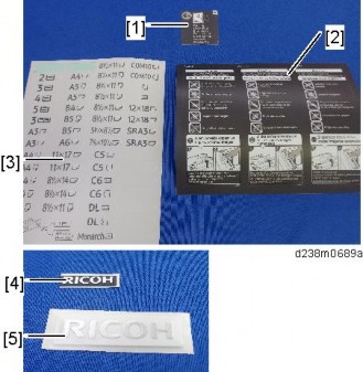
If the IP address cannot be found (DHCP server), use the MAC address. This is the number printed on the seal attached to the printed circuit board for the USB server.

Use "RX" + the option’s MAC address and access a web browser. Example: http://RX0080926A3264


Ping "RX" + "MAC address" from the command prompt on a windows PC which is on the same network as the mainframe.
When installing the USB Device Server Option Type M19, the installation status is not shown on the Configuration Page.
The customer should keep the slot cover which were removed.
When this option is properly installed and recognized by the main machine, the LED indicators light up under the following conditions.

No. | Light Color | Lights Up When: |
1 | Green and Yellow | 1000BASE-T operates |
2 | Green | 10BASE-T operates |
3 | Yellow | 100BASE-TX operates |
Installation
This section describes how to set an IP address on this option manually. Note that you can set an IP address which is not only on the same network segment but also on a different network segment to share a single printer with devices in multiple networks.
You cannot change the IP address for this option from the operation panel of the main machine. The setting must be done from a web browser on your PC.
The network setting of this option is initially assigned as follows: IP address: 192.168.100.100 / Subnet mask: 255.255.255.0
The network setting of your PC must be in the same network segment to change the network setting of this option.
The setting screen for this option appears.


Installation
No | Items | Q’ty | Remarks |
1 | Extended USB Board | 1 |

When installing this option, turn OFF the main power and unplug the power cord from the wall socket. If installing without turning OFF the main power, an electric shock or a malfunction may occur.
Do not put your hand into the controller box. It will result in a malfunction or injury.
Before doing any work, touch a metal object to discharge static electricity from the body.

The customer should keep the slot cover which were removed.
Installation
No. | Description | Q’ty | Remarks |
1 | IEEE 1284 Interface Board | 1 | |
2 | FCC document | 1 | |
3 | Notes for users | 1 |

When installing this option, turn OFF the main power and unplug the power cord from the wall socket. If installing without turning OFF the main power, an electric shock or a malfunction may occur.
Do not put your hand into the controller box. It will result in a malfunction or injury.
Before doing any work, touch a metal object to discharge static electricity from the body. There is a possibility that the IEEE 1284 Interface Board may malfunction due to static electricity.

The customer should keep the slot cover which were removed.
Installation
This option is not available in China, Taiwan, and Korea.
No. | Description | Q’ty |
1 | IEEE802.11a/g/n Unit | 1 |
2 | Clamps | 2 |
3 | Velcro Fasteners | 8 |
4 | Notes for Users | 2 |

Since disassembly/alteration of a wireless LAN board is illegal, during service replacements, replace the whole PCB assembly.
Be sure to give the provided leaflet to the customer.
When installing this option, turn OFF the main power and unplug the power cord from the wall socket. If installing without turning OFF the main power, an electric shock or a malfunction may occur.
Do not put your hand into the controller box. It will result in a malfunction or injury.
Before doing any work, touch a metal object to discharge static electricity from the body. There is a possibility that the extension wireless LAN board may malfunction due to static electricity.
When using wireless LAN (IEEE802.11 b/g/n:2.4-GHz band), this radio product uses the 2.4-GHz band. Check that industrial, scientific and medical devices using the same frequency bands, such as a microwave oven or a cordless telephone, are not used nearby.
If there is interference, communication may become unstable. Check that there are no devices likely to cause interference in the surrounding area.


Press the extended wireless LAN board firmly in, and check it is firmly connected.
Installation
The customer should keep the slot cover which were removed.


Take care to loop it around so that it does not interfere with other options or I/F cables.
Go into the User Tools mode and do the procedure below. These settings take effect every time the machine is powered on.
IEEE 802.11a/g/n function is disabled while using Ethernet.
Select "Interface Settings"> "Network" > "LAN Type". The "LAN Type" (default: Ethernet) must be set for either Ethernet or wireless LAN.
For mainly Europe and Asia
2,412 - 2,462 MHz (1 - 11 channels)
5,180 - 5,240 MHz (36, 40, 44 and 48 channels)
(default: 11)
In some countries, only the following channels are available: 2,412 - 2,462 MHz (1 - 11 channels)
For mainly North America
2,412 – 2,462 MHz (1 - 11 channels)
5,180 – 5,240 MHz (36, 40, 44 and 48 channels)
(default: 11)
The "WEP" (Wired Equivalent Privacy) setting is designed to protect wireless data transmission. The same WEP key is required on the receiving side in order to unlock encoded data. There are 64 bit and 128 bit WEP keys.
Range of Allowed Settings: 64 bit: 10 characters
128 bit: 26 characters
Specify "WPA2" when "Communication Mode" is set to "Infrastructure Mode". Set the "WPA2 Authent. Method".
WPA2 Authent. Method:
Select either "WPA2-PSK" or "WPA2".
If you select "WPA2-PSK", enter the pre-shared key (PSK) of 8-63 characters in
ASCII code.
Installation
When "WPA2" is selected, authentication settings and certificate installation settings are required.
Press "Restore Factory Defaults" to initialize the wireless LAN settings.
The following SP commands and UP modes can be set for IEEE 802.11
SP No. | Name | Function |
SP5-840-006 | Channel MAX | Sets the maximum range of the channel settings for the country. |
SP5-840-007 | Channel MIN | Sets the minimum range of the channels settings allowed for your country. |
SP5-840-008 | Transmission Speed | Sets the transmission speed. Auto, 54 Mbps, 48 Mbps, 36 Mbps, 24 Mbps, 18 Mbps, 12 Mbps, 9 Mbps, 6 Mbps, 11 Mbps, 5.5 Mbps, 2 Mbps, 1 Mbps (default: Auto). |
SP5-840-011 | WEP Key Select | Used to select the WEP key (Default: 00). |
UP mode | Name | Function |
SSID | Used to confirm the current SSID setting. | |
WEP Key | Used to confirm the current WEP key setting. | |
WEP Mode | Used to show the maximum length of the string that can be used for the WEP Key entry. | |
WPA2 Authent. Method | Used to confirm the current WPA authentication setting and preshared key. |
No. | Description | Q’ty |
1 | File Format Converter | 1 |
2 | Notes for Users | 1 |

Installation
When installing this option, turn OFF the main power and unplug the power cord from the wall socket. If installing without turning OFF the main power, an electric shock or a malfunction may occur.
Do not put your hand into the controller box. It will result in a malfunction or injury.
Before doing any work, touch a metal object to discharge static electricity from the body. There is a possibility that the board may malfunction due to static electricity.

The customer should keep the slot cover which were removed.
No. | Description | Q’ty |
1 | Bluetooth Module | 1 |
- | CD-ROM | 2 |

When installing this option, turn OFF the main power and unplug the power cord from the wall socket. If installing without turning OFF the main power, an electric shock or a malfunction may occur.
Do not put your hand into the controller box. It will result in a malfunction or injury.
There is no difference between the left and right USB ports.

Installation
No. | Description | Q’ty | Remarks |
1 | Memory Unit (DDR3L-DIMM 4G) | 1 |

When installing this option, turn OFF the main power and unplug the power cord from the wall socket. If installing without turning OFF the main power, an electric shock or a malfunction may occur.


Push the release latches [B] until they slip into the notch on the edge of the SDRAM.

Installation
No. | Description | Q’ty | Remarks |
1 | Enhanced Security HDD | 1 | |
- | EMC Address | 1 |

When installing this option, turn OFF the main power and unplug the power cord from the wall socket. If installing without turning OFF the main power, an electric shock or a malfunction may occur.


Installation


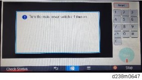
Do not touch the power switch while the hard disk format is in progress. Wait for the machine to tell you that the formatting is finished.

Installation
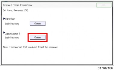
If the HDD Authentication Code is not registered, the function of the enhanced security HDD is not activated.
SP5-846-040 | UCS Setting: Addr Book Migration(USB->HDD) |
Copies the address book to the hard disk from the controller board. [Execute] | |
SP5-846-041 | UCS Setting: Fill Addr Acl Info |
This SP must be executed immediately after installation of an HDD unit in a basic machine that previously had no HDD. The first time the machine is powered on with the new HDD installed, the system automatically takes the address book from the NVRAM and writes it onto the new HDD. However, the new address book on the HDD can be accessed only by the system administrator at this stage. Executing this SP by the service technician immediately after power on grants full address book access to all users. [Execute] |
No. | Description | Q’ty | For This Model |
1 | PCB: MKB | 1 | |
2 | Harness IOB to MKB | 1 | Not used |
3 | Screws M3x8 | 2 | Not used |
4 | Screws M3x6 | 4 | Not used |
5 | Standoffs | 4 | |
6 | Clamp | 1 | Not used |
7 | Wire Band | 1 | Not used |
When installing this option, turn OFF the main power and unplug the power cord from the wall socket. If installing without turning OFF the main power, an electric shock or a malfunction may occur.

Installation

Do not use the harness that is provided with the accessories for the interface cable.
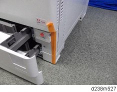
Connect the harness of the optional counter to the black connector [C].
Installation
No. | Description | Q’ty | Remarks |
- | Screw: M3X8 | 1 | |
- | Binding Self-Tapping Screw: M4X8 | 3 | |
- | Clamp:LWS-1211Z | 2 | |
- | Clamp:NK-3N | 1 | |
- | Double Sided Tape | 2 | |
- | Key Counter Plate Nut | 2 | |
- | Key Counter Harness | 1 |
When installing this option, turn OFF the main power and unplug the power cord from the wall socket. If installing without turning OFF the main power, an electric shock or a malfunction may occur.

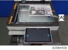
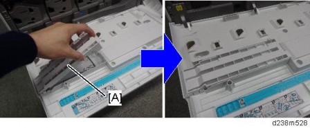
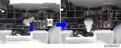
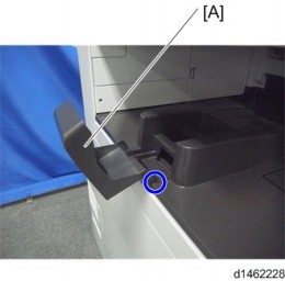
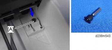
When installing, insert the projections [A] in the holes [B], taking care not to trap the harness inside.
Installation
Installation

Check the quantity and condition of the accessories against the following list.
No. | Description | Q'ty | For This Model |
1 | Screw: M3 x 8 | 2 | Yes |
2 | Screw: M3 x 14 | 1 | Not used |
3 | Screw: M4 x 25 | 1 | Yes |
4 | Tapping Screw: M3 x 10 | 3 | Yes |
5 | Upper Tray | 1 | Yes |
6 | Lower Tray | 1 | Yes |
7 | Tray Bracket | 1 | Yes |
8 | Clamp | 5 | Yes |

When installing this option, turn OFF the main power and unplug the power cord from the wall socket. If installing without turning OFF the main power, an electric shock or a malfunction may occur.
Installation

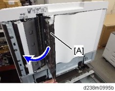
Remove the hook at the top, and then slide the cover towards the rear.
Make the screw holes to be smaller than the screw size.
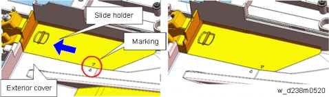
For this model, use the screw holes marked "3" on the table bracket.


The USB cable is not supplied. Use a commercially available USB cable.

Installation

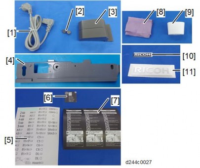
No. | Description | Q'ty | Remarks |
1 | Corner Cover | 1 | |
2 | Reader Spacer | 1 | |
3 | Reader Cover | 1 | |
4 | Reader | 1 | |
5 | Sponge Cushions | 2 | |
6 | Ferrite Core (Black) | 1 | |
7 | Interface Cable | 1 |

Installation
When installing this option, turn OFF the main power and unplug the power cord from the wall socket. If installing without turning OFF the main power, an electric shock or a malfunction may occur.

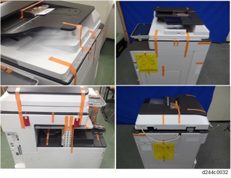
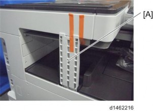
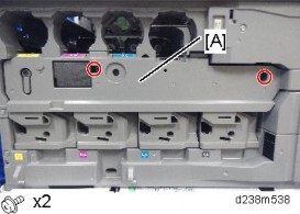
Remember that there is a tab at the positions of the red arrows.
Rotate the operation panel [B] upward to a horizontal position, and then detach the front upper cover [A].
Use the screws removed in the previous step.

Installation
Attach the ferrite core 6 cm [A] away from the end of the cable.
By doing so, it becomes easier to put the ferrite core inside the reader cover in step 12.


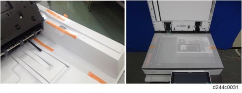
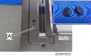
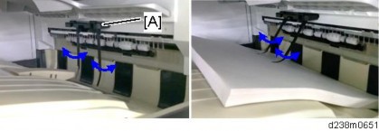
Make sure to turn the USB cable as shown so that it threads through the notch in the spacer [A].


Installation
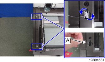
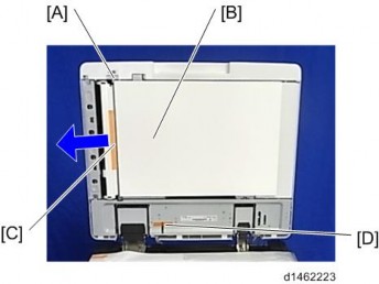
Make sure that the cable is not loose between the connector and hinge [A] and the hinge and clamp [B].

Installation
No. | Description | Q’ty | Remarks |
1 | Corner Cover | 1 | |
2 | IC Card Reader Spacer | 1 | |
3 | IC Card Reader Table | 1 | |
4 | Sponge | 2 |

When installing this option, turn OFF the main power and unplug the power cord from the wall socket. If installing without turning OFF the main power, an electric shock or a malfunction may occur.
An IC card reader and a USB cable are not included with this unit. The customers must obtain these themselves, and the technicians must install them.
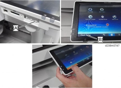
There are 2 ways to connect the USB cable of the IC card. One is to the machine USB slot which is the same way as the previous machine, and another is to the smart operation panel USB slot.

Remember that there is a tab at the positions of the red arrows.
Rotate the operation panel [B] upward to a horizontal position, and then detach the front upper cover [A].


Installation
Use the screws removed in the previous step.

This cable is not included in this unit. The user may need to provide it.
There are three ribs on the back side of the table.
Installation
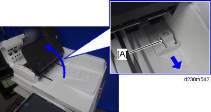
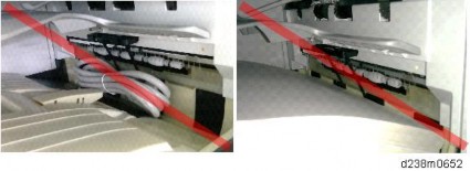
The USB cable should be turned as the following photo shows.
Tuck in the excess length portion of the cable in the space over the controller box.

Installation

Remember that there is a tab at the positions of the red arrows.
Rotate the operation panel [B] upward to a horizontal position, and then detach the front upper cover [A].

Use the screws removed in the previous step.