ARDF DF3090 (D779)


2.1.3 SP6-901-002 (SETTING TO GIVE PRIORITY TO STACKABILITY)
To improve the alignment of the delivered originals, select to give priority to stackability in the following SP. This will reduce the originals’ delivery speed and improve their stackability.
SP6-901-002 (Setting to give priority to stackability): for DF3090 0: Higher throughput (default)
1: Higher stackability
REVISION H IST ORY | ||
Page | Date | Added/ Updated/ New |
None | ||
REPLACEMENT AND ADJUSTMENT 1
REAR COVER 1
PRECAUTIONS CONCERNING STABILIZERS 1
REAR COVER 1
TRAY LIFT MOTOR (UPPER) 2
TRAY LIFT MOTOR (UPPER) 2
TRAY LIFT MOTOR (LOWER) 3
TRAY LIFT MOTOR (LOWER) 3
TRANSPORT MOTOR 4
TRANSPORT MOTOR 4
PAPER FEED MOTOR 5
PAPER FEED MOTOR 5
CONTROLLER BOARD 6
CONTROLLER BOARD 6
TRANSPORT SENSOR, UPPER LIMIT SENSOR, PAPER END SENSOR 7
TRANSPORT SENSOR 7
UPPER LIMIT SENSOR 8
PAPER END SENSOR 8
2ND PAPER FEED UNIT 9
2ND PAPER FEED UNIT 9
1ST PAPER FEED UNIT 13
Paper Feed Transport Mechanism 19
Tray Base Plate Lift 21
Paper size detection 23
Remaining paper detection/paper end detection 25
This manual uses several symbols and abbreviations. The meaning of those symbols and abbreviations are as follows:
| Clip ring |
| Screw |
| Connector |
| Clamp |
SEF | Short Edge Feed [A] |
LEF | Long Edge Feed [B] |

Trademarks
Microsoft®, Windows®, and MS-DOS® are registered trademarks of Microsoft Corporation in the United States and /or other countries.
PostScript® is a registered trademark of Adobe Systems, Incorporated.
PCL® is a registered trademark of Hewlett-Packard Company. Ethernet® is a registered trademark of Xerox Corporation.
PowerPC® is a registered trademark of International Business Machines Corporation.
Other product names used herein are for identification purposes only and may be trademarks of their respective companies. We disclaim any and all rights involved with those marks.
PAPER FEED UNIT PB3210/PB3220 (D787)
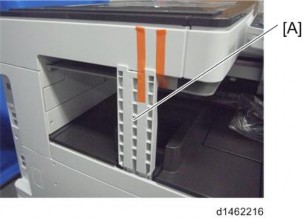
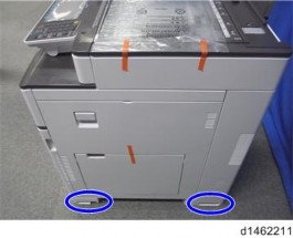
PRECAUTIONS CONCERNING STABILIZERS
The stabilizers are necessary for meeting the requirements of IEC60950-1, the international standard for safety.
The aim of these components is to prevent the products, which are heavy, from toppling as a result of people running into or leaning on the products, which can lead to serious accidents such as persons becoming trapped under the product. (U.S.: UL60950-1, Europe: EN60950-1) Therefore, removal of such components must always be with the consent of the customer.
Do not remove them at your own judgment.
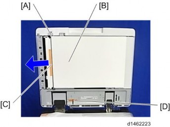
REAR COVER
Securing brackets [A] ![]() ×2)
×2)

Rear cover [A] ![]() ×2)
×2)

TRAY LIFT MOTOR (UPPER)
Rear cover (page 1)
Tray lift motor (upper) [A] ![]() ×2,
×2,![]() ×1)
×1)

PAPER FEED UNIT PB3210/PB3220 (D787)
TRAY LIFT MOTOR (LOWER)
Rear cover (page 1)
Tray lift motor (lower) [A] ![]() ×2,
×2,![]() ×1)
×1)

TRANSPORT MOTOR
Rear cover (page 1)
Transport motor [A] ![]() ×2,
×2,![]() ×1)
×1)

PAPER FEED UNIT PB3210/PB3220 (D787)
PAPER FEED MOTOR
Rear cover (page 1)
Paper feed motor [A] ![]() ×2,
×2,![]() ×1)
×1)

CONTROLLER BOARD
Rear cover (page 1)
Controller board [A] ![]() ×4,
×4,![]() ×10)
×10)

PAPER FEED UNIT PB3210/PB3220 (D787)
TRANSPORT SENSOR
2nd paper feed unit (page 9), 1st paper feed unit (page 13)
Transport sensor bracket [A] ![]() ×1)
×1)

Transport sensor [A] ![]() ×1)
×1)

UPPER LIMIT SENSOR
2nd paper feed unit (page 9), 1st paper feed unit (page 13)
Upper limit sensor [A] ![]() ×1)
×1)

PAPER END SENSOR
2nd paper feed unit (page 9), 1st paper feed unit (page 13)
Paper end sensor [A] ![]() ×1)
×1)

PAPER FEED UNIT PB3210/PB3220 (D787)
2ND PAPER FEED UNIT
Pull out the paper trays.
Rear cover (page 1)
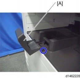
Right front cover [A] ![]() ×1)
×1)

Right rear cover [A] ![]() ×1)
×1)

Stabilizer covers [A] ![]() ×2)
×2)

Right lower cover [A] ![]() ×2)
×2)
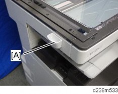
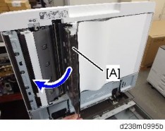
Open the transport cover [A].

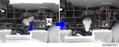
Stopper [A] ![]() ×1)
×1)

PAPER FEED UNIT PB3210/PB3220 (D787)
Interlock switch cover [A] ![]() ×1)
×1)

Paper feed guide plate [A]

Harness cover [A] ![]() ×2)
×2)

12. Harness [A] ![]() ×1,
×1,![]() ×4)
×4)
13. 2nd Paper feed unit [A] ![]() ×2)
×2)
PAPER FEED UNIT PB3210/PB3220 (D787)
1ST PAPER FEED UNIT
1. 2nd Paper feed unit (page 9) 2. Harness [A] ![]() ×1,
×1,![]() ×6)
×6)
Guide plate ![]() ×1)
×1)
1st Paper feed unit [A] ![]() ×2)
×2)
PAPER FEED UNIT PB3210/PB3220 (D787)
PICK-UP ROLLER, FEED ROLLER, FRICTION ROLLER
2nd paper feed unit (page 9), 1st paper feed unit (page 13)
Holder [A] ![]() ×1)
×1)
Pick-up roller [A]
Feed roller [A]
Friction roller [A] ![]() ×1)
×1)
PAPER FEED UNIT PB3210/PB3220 (D787)
PARTS LAYOUT

No. | Description |
1 | Paper size switch |
2 | Tray set switch |
3 | Pick-up roller |
4 | Feed roller |
5 | Transport roller |
6 | Friction roller |
No. | Description | No. | Description |
1 | Paper size switch | 8 | Anti-condensation heater |
2 | Controller board | 9 | Paper feed sensor |
3 | Tray set switch | 10 | Paper end sensor |
4 | Tray lift motor | 11 | Transport sensor |
5 | Paper feed motor | 12 | Upper limit sensor |
6 | Transport motor | 13 | Pick-up solenoid |
7 | Transport cover open/close switch |
PAPER FEED UNIT PB3210/PB3220 (D787)
MECHANISM
Paper Feed Separation Mechanism
Paper feed is an RF paper feed system. The paper feed unit comprises a pick-up roller, feed roller and friction roller. These rollers are high durability.
In the RF system, paper separation is assisted by the resistance of a separation roller with a torque limiter (reverse drive is not performed).
Drive Mechanism
The pick-up roller and feed roller are driven by the paper feed motor [A]. The transport roller is driven by the transport motor [B]. The friction roller is not driven.
Friction Roller/Pick-up Roller Release Mechanism
When the paper feed tray is set, the friction roller comes in contact with the feed roller, and the pick-up roller contacts the uppermost sheet of paper.
However, when the paper feed tray is pulled out, to prevent paper from dropping out, the contact between the feed roller and friction roller, and between pick-up roller and paper is released.
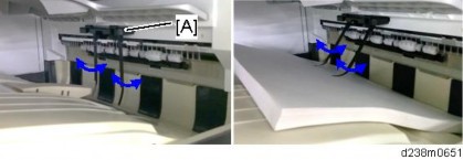
Paper Feed Transport Mechanism
In this MFP, to maintain a fixed clearance between sheets, a paper feed sensor is provided near the pickup roller, which adjusts the paper feed timing.

The paper feed motor turns ON, and supplies the first sheet.
To prevent the next sheet from being fed, the pick-up solenoid switches ON just before the trailing edge of the first sheet leaves the pickup roller, and the pickup roller separates from the paper surface.
Slightly before the trailing edge of the first sheet leaves the paper feed roller, the paper feed motor switches OFF.
However, at this time, when the paper feed sensor detects no sheet (when the second sheet is not fed to the paper feed sensor position), pre-feed is performed without switching the paper feed motor OFF.
Pre-feed is as follows.
The pickup solenoid switches OFF, and the second sheet of paper is fed to the paper feed sensor position.
When the trailing edge of the second sheet passes the feed roller, the paper feed motor is switched OFF. The pickup solenoid remains OFF.
Just when the trailing edge of the first sheet passes the paper feed roller, the pickup solenoid is switched OFF, and the pickup roller is brought in contact with the paper surface.
When the first sheet is fed a predetermined distance by the downstream transport roller, the paper feed motor is switched ON to supply the second sheet.
PAPER FEED UNIT PB3210/PB3220 (D787)
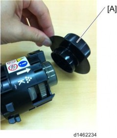
Tray Base Plate Lift
When the paper feed tray is set in the main unit, the set switch switches ON, and it is detected that the tray is set. At this time, the coupling of the lift motor engages with the shaft at the rear of the tray, the motor rotates, and the tray base plate is lifted up. The paper surface pushes up the Pickup roller, the tray base plate is lifted until the upper limit sensor switches OFF (blocked), and the machine enters the standby mode.
When the paper feed tray is removed, the coupling is disengaged, and the base plate descends. At this time, the lift motor rotates until the coupling returns to the home position.

No. | Description | No. | Description |
1 | Lift motor | 3 | Tray rear side shaft |
2 | Coupling | 4 | Tray base plate |

No. | Description | No. | Description |
1 | Upper limit sensor | 2 | Pick-up roller |
PAPER FEED UNIT PB3210/PB3220 (D787)
Paper size detection
The end fence interlocks mechanically with the size detection actuator, and when the end fence is moved, the size detection actuator also moves.
When the paper feed tray is set, 4 size detection switches switch ON/OFF depending on the position of the size detection actuator. Paper size is detected by the detected combination of these switches.

No. | Description | No. | Description |
1 | End fence | 3 | Size detection actuator |
2 | Paper size switch | 4 | Tray set switch |
Paper size switch operation
Paper size | Paper size switch | |||
SW4 | SW3 | SW2 | SW1 | |
SRA3 (12”×18”) | 1 | 0 | 1 | 0 |
A3 (DLT) | 0 | 1 | 0 | 0 |
B4 (LG) | 0 | 0 | 1 | 1 |
0 | 1 | 1 | 1 | |
A4_SEF | 1 | 1 | 1 | 0 |
LT_SEF | 1 | 1 | 0 | 0 |
B5_SEF | 1 | 0 | 0 | 0 |
A4_LEF (LT_LEF) | 0 | 0 | 0 | 1 |
B5_LEF (Exe_LEF) | 0 | 0 | 1 | 0 |
A5_LEF | 0 | 1 | 0 | 1 |
PAPER FEED UNIT PB3210/PB3220 (D787)
Remaining paper detection/paper end detection
Remaining paper detection
Detection of paper remaining in the paper feed tray is performed by a combination of ON/OFF (contact/non-contact) of contact-type remaining detection plates (printed circuits) CN-3, CN-5. When the amount of remaining paper decreases, and the tray lift motor rotates, the remaining paper sensors CN-3 and CN-5 in the motor are turned ON/OFF.
The following 4 levels of remaining paper can be detected:
Amount remaining | 100% | 70% | 30% | 10% |
CN-3 | OFF | ON | ON | OFF |
CN-5 | OFF | OFF | ON | ON |
Control panel remaining paper display | 4 bars | 3 bars | 2 bars | 1 bar |
Paper end detection
When the paper feed tray is empty, the paper end sensor switches ON (unblocked) due to the end feeler.

No. | Description | No. | Description |
1 | Paper end sensor | 3 | Slot in the tray base plate |
2 | End feeler |
R EVI SIO N HIS TORY | ||
Page | Date | Added/ Updated/ New |
None | ||
REPLACEMENT AND ADJUSTMENT 1
SMART OPERATION PANEL 1
OPERATION PANEL UNIT 1
CPU BOARD 5
MICRO COMPUTER BOARD 8
WI-FI MODULE 10
LCD 11
SPEAKER 13
MICROPHONE 14
MECHANISM 16
OVERVIEW 16
SYSTEM COMPONENTS 16
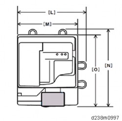
Hardware Specifications 16
Software Specifications 21
Communication specifications 22
Application Specifications 25
PANEL COMPONENTS/SCREEN LAYOUT 30
Components of the Control Panel 30
Panel display 32
ELECTRICAL COMPONENTS 35
Touch panel 35
CONTROLLING THE POWER SUPPLY 37
EXITING ENERGY SAVING MODES 37
SCREEN STARTUP MODE 37
Startup Modes 37
Changing the Screen Startup Mode 37
How the Control Panel Starts Up 38
How the Screen Shuts Down When Quick mode Is Selected 39
SHUTDOWN FUNCTIONS 40
Normal Shutdown 41
SM i SOP 2ndGEN
Other Shutdown Functions 41
SYSTEM MAINTENANCE 42
SYSTEM MAINTENANCE 42
MAINTENANCE MODES 42
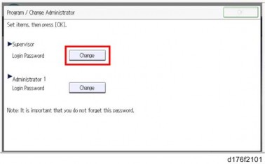
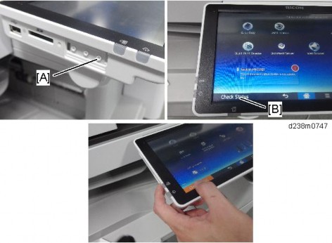
LOGIN TO/LOGOUT FROM CONTROL PANEL SERVICE MODE 43
Login 43
Login Status Indicator 43
Logout 44
When Entry to Service Mode Is Prohibited by the Administrator 44
SERVICE MODE MENU 45
WIRELESS & NETWORKS 45
DEVICE 47
SYSTEM 48
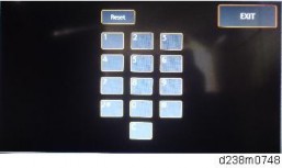
PANEL SELF CHECK 51
LED Check 52
Key Check 52
LCD Check 53
Speaker Check 54
TouchPanel Check 55
TouchPanel Calibration 56
MultiTouch Calibration 57
Wireless LAN Check 58
Bluetooth Check 59
RECOVERY MODE 60
SPECIAL KEY COMBINATIONS 61
SOFTWARE UPDATE 62
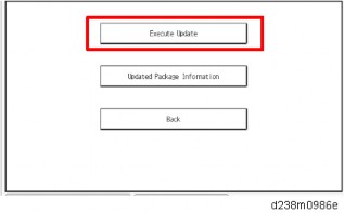
UPDATING THE SMART OPERATION PANEL 62
INSTALLATION/UPDATE FROM AN SD CARD 64
Updating the Smart Operation Panel Firmware 64
Installing/Updating an Application 67
PACKAGE UPDATE 67
When Installation/Update Is Prohibited 67
INSTALLATION/UPDATE FROM THE EDC SERVER 68
Check Server Connect 68
Installation 69
Activation 69
Update 70
APPLICATION SITE 70
SOP 2ndGEN ii SM
TROUBLESHOOTING 71
TROUBLESHOOTING 71
SOFTWARE UPDATE ERRORS 71
Errors that occur during application update from an SD card 71
Errors that occur during update from the eDC Server 72
Errors that occur during remote (batch file) update 73
ERRORS THAT OCCUR WHEN THE CONTROL PANEL DOWNLOADS DATA FROM THE CONTROLLER AT STARTUP 79
This manual uses several symbols and abbreviations. The meaning of those symbols and abbreviations are as follows:
| Clip ring |
| Screw |
| Connector |
| Clamp |
SEF | Short Edge Feed |
LEF | Long Edge Feed |

Short Edge Feed (SEF)
Long Edge Feed (LEF)
Trademarks
Microsoft®, Windows®, and MS-DOS® are registered trademarks of Microsoft Corporation in the United States and /or other countries.
PostScript® is a registered trademark of Adobe Systems, Incorporated.
PCL® is a registered trademark of Hewlett-Packard Company. Ethernet® is a registered trademark of Xerox Corporation.
PowerPC® is a registered trademark of International Business Machines Corporation. Android is a trademark of Google Inc.
Other product names used herein are for identification purposes only and may be trademarks of their respective companies. We disclaim any and all rights involved with those marks.
OPERATION PANEL UNIT
Turn off the main power switch of the MFP and disconnect the power cord.
After replacing, make sure that all disconnected harnesses are connected up again and secured in their clamps (if the MFP has harnesses).

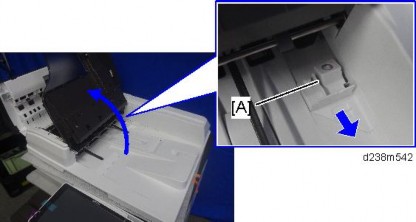
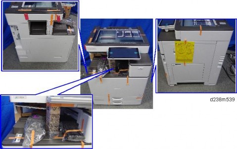
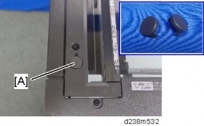
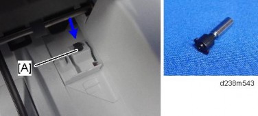
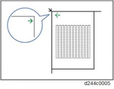
When handling the operation panel cable, hold down the connector of the cable with your finger as shown in the picture to prevent excessive force from being applied to the connector of the PCB.
If excessive force is applied to the connector of the PCB in the direction of the arrow, connection failure may occur.
For machines manufactured in October 2016 or later, a bracket [A] will be added to cover the connector of the cable.
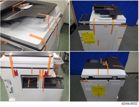
Remove the operation panel unit from the MFP.
For details about how to remove the operation panel unit, refer to the service manual for the MFP.
Operation panel arm bracket [A] ![]() ×4)
×4)
By factory default, switches No.3 and No.7 of the DIP switch [A] on the micro computer board are set to ON. When installing the operation panel unit, make sure that the DIP switch setting is correct for the MFP on which you are installing the panel.

The correct DIP switch setting depends on the MFP. Note the DIP switch settings of the old operation panel unit before replacing, and apply the same settings to the new Smart Operation Panel. (Below are two examples for DIP switch settings.)
When No.3 and No.7 are set to ON | When only No.3 is set to ON |
|
|
This is the factory default setting of a service part
If the DIP switch setting is wrong, SC672 will be displayed.
After replacing the operation panel unit, make sure that the latest version of the firmware is installed on the Smart Operation Panel. Update it if necessary (page 62 "Updating the Smart Operation Panel").
CPU BOARD
Operation panel unit (page 1)
Bottom cover [A] ![]() ×4)
×4)
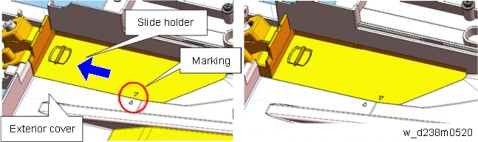
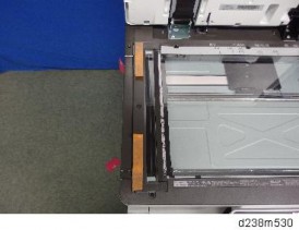
There are four hooks inside the operation panel unit. Before removing the operation panel bottom cover, check the photos below.

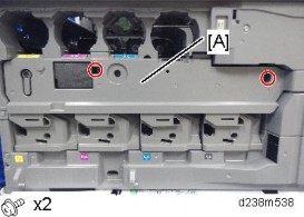
Base bracket [A] ![]() ×9)
×9)

Remove the fixing screws ![]() ×4) on the CPU board [A], and remove the CPU board from the micro computer board.
×4) on the CPU board [A], and remove the CPU board from the micro computer board.
Make sure that the orientation of the connector is correct when attaching the CPU board.
Lift the fastener of the LCD I/F cable on the CPU board side.
CPU board [A] (LCD I/F cable ×1)
After replacing the CPU board, make sure that the latest version of the firmware is installed on the Smart Operation Panel. Update it if necessary. (page 62 "Updating the Smart Operation Panel")
MICRO COMPUTER BOARD
Operation panel unit (page 1)
CPU board (page 5)
Remove the FFC from the micro computer board ![]() ×1).
×1).
Pull out the black part to unlock the connector, and then remove the FFC.
Micro computer board [A] ![]() ×1,
×1, ![]() ×2)
×2)

By factory default, switches No.3 and No.7 of the DIP switch [A] on the micro computer board are set to ON. When installing the operation panel unit, make sure that the DIP switch setting is correct for the MFP on which you are installing the panel.

The correct DIP switch setting depends on the MFP. Note the DIP switch settings of the old operation panel unit before replacing, and apply the same settings to the new Smart Operation Panel. (Below are two examples for DIP switch settings.)
When No.3 and No.7 are set to ON | When only No.3 is set to ON |
|
|
This is the factory default setting of a service part
If the DIP switch setting is wrong, SC672 will be displayed.
After replacing the micro computer board, perform the following checks:
LED Check (page 52)
Key Check (page 52)
WI-FI MODULE
Operation panel unit (page 1)
Bottom cover [A] ![]() ×4)
×4)

Base bracket [A] ![]() ×9)
×9)
Wi-Fi module [A] ![]() ×1)
×1)

After replacing the Wi-Fi module, perform the following checks:
Wireless LAN Check (page 58)
Bluetooth Check (page 59)
LCD
Operation panel unit (page 1)
CPU board (page 5)
Micro computer board (page 8)
Speaker [A] ![]() ×2)
×2)
Lift the fastener of the LCD I/F cable.
LCD I/F cable (cable ×1)

Remove the tapes for fixing the microphone harness (tape ×3).
8. LCD [A] ![]() ×4)
×4)

After replacing the LCD, perform the following checks.
LCD Check (page 53)
TouchPanel Check (page 55)
Perform "TouchPanel Calibration" (page 56) and "MultiTouch Calibration" (page 57) of the Self Check function.
SPEAKER
Operation panel unit (page 1)
Bottom cover [A] ![]() ×4)
×4)
3. Speaker [A] ![]() ×2,
×2, ![]() ×1)
×1)
After replacing the speaker, perform the following check.
Speaker Check (page 54)