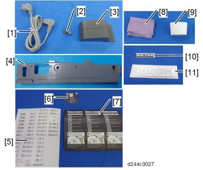
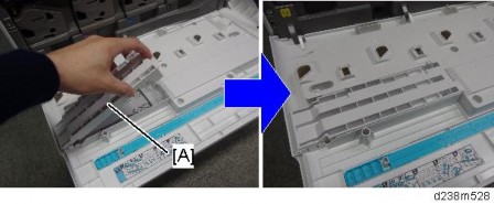
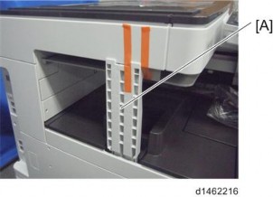
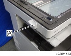
Paper exit cover (page 7)
INTERNAL FINISHER SR3180 (D766)
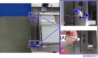
Controller board [A] ![]() ×4,
×4, ![]() ×all)
×all)


No. | Description | No. | Description |
1 | Paper exit tray | 8 | Entrance sensor |
2 | Paper exit roller/paper exit belt | 9 | Trailing edge presser |
3 | Paper exit sensor | 10 | Stapler drive motor |
4 | Junction gate | 11 | Stapler |
5 | Shift roller | 12 | Stapler home position sensor |
6 | Side-to-side registration sensor | 13 | Paper exit pressure motor |
7 | Reverse roller |
INTERNAL FINISHER SR3180 (D766)


No. | Description | No. | Description |
1 | Open/close door switch | 2 | HP sensor |
No. | Description | No. | Description |
1 | Paper exit full sensor 2 (staple) | 5 | Transport motor |
2 | Paper exit full sensor 1 | 6 | Paper exit pressure HP sensor |
3 | Shift HP sensor | 7 | Junction gate motor |
4 | Shift motor |
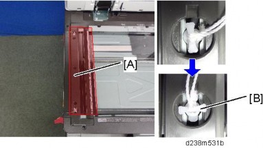
Tray full detection mechanism

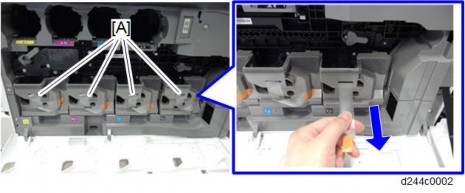
When the paper exit full sensor 1 [A] or the paper exit full sensor 2 (staple) [B] detects paper, the paper exit tray is full. Paper feed is stopped temporarily while the tray is full, and is restarted after the paper is removed.
The paper exit full sensor 1 is at the center of the main scan (side-to-side), and detects the total quantity of paper in the paper exit tray.
If the paper is stapled, the height of the paper around the stapled area is higher than that of the other areas. The paper exit full sensor 2 (staple) is located at the stapling area, and detects the quantity of stapled paper.
Straight paper exit/shift paper exit mechanism


INTERNAL FINISHER SR3180 (D766)
Paper from the main machine is transported to the paper exit roller [B] and paper exit belt [A] via the shift rollers ([C] and [D]). The transport motor drives the shift rollers, reverse rollers and paper exit rollers.
After passing through the paper exit roller of the main machine, to shift the paper from side to side, the shift rollers ([C] and [D]) nip the sheets and the shift motor moves the paper towards the front or rear of the machine.
If the paper is still held by the paper exit rollers, this will stop the paper from shifting, so the paper exit rollers ([A] and [B]) are moved from their home (strong pressure) positions to their pressure release positions.
Shift mechanism

Shift roller operation timing
Paper is shifted when the distance between the trailing edge and the paper exit roller on the main machine is 10mm (the entrance sensor detects the leading edge of the paper).
The shift motor [A] rotates clockwise/anti-clockwise to shift the paper towards the front/rear of the machine.
The shift amount is 20mm when shifting towards the front, and 10mm when shifting towards the back.
The home position is located at the back end of the shift area, and is detected by the shift roller HP sensor [B].
Paper exit roller/paper exit belt release mechanism

Pressure release timing of the paper exit rollers
Waiting (before paper is received): Strong pressure
When paper is transported: Pressure released
When paper shift is completed (shift motor stops): Strong pressure
When paper is transported, the paper exit rollers/paper exit belt ([A] and [D]) are at the pressure release position so that they do not interfere with paper shifting.
When paper shift is completed, the rollers are moved to the strong pressure position for paper transportation and paper exit.
Positions of the paper exit roller/paper exit belt
HP (strong pressure)
Pressure release position
Weak pressure position
The paper exit pressure motor [B] rotates clockwise/anti-clockwise to drive the paper exit drive belt [D] to the strong pressure or weak pressure positions.
The paper exit pressure HP sensor [C] detects the home position.
Details of each position
Home position (strong pressure position)
INTERNAL FINISHER SR3180 (D766)
This is used for paper transportation and paper exit. The pressure increased using the motor [B], and the paper exit roller (drive) [A] and the paper exit belt (driven) [D] come into contact in order to nip the paper firmly.
[C] is the paper exit pressure HP sensor.

Pressure release position
The nip of the paper exit roller/paper exit belt is released so that they do not interfere with paper shift.

Weak pressure position
This is used during stapling, when there is already paper stacked in the paper exit tray, and more paper is being transported.
The motor [A] lowers the pressure, and the position of the paper exit belt (driven) is moved so that the middle part of the belt comes in contact with the paper exit roller (drive).
The weak pressure position is for preventing smudges or stains caused by paper rubbing against the paper that is already stacked.

Staple eject mechanism
INTERNAL FINISHER SR3180 (D766)
Transport/adjustment of paper position (home position)

This finisher does not have a jogger. Paper position (side-to-side) is aligned using sensors, by registration adjustment during paper transportation.
The leading edge of the paper transported from the main machine is detected by the entrance sensor [D]. After the trailing edge has passed through the paper exit rollers of the main machine, the paper is transported by the shift rollers ([A] and [B]) for shifting. The paper is shifted to the position where the side-to-side registration sensor [C] detects the rear edge of the paper (as viewed from the front of the machine). During paper shifting, the paper exit roller and paper exit belt move to the pressure release position.
Stacking (Position B)

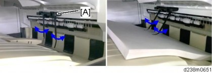
After shifting is completed, the paper exit rollers move to the strong pressure position and received the paper from the shift rollers. After the trailing edge of the paper has passed the junction gate, the paper exit roller rotates in the opposite direction. Paper is transported to the stacking area, and then passed through the reverse rollers [H].
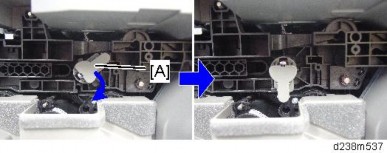
At this time, the junction gate [J] moves to the lower position (the gate’s edge is raised, as shown by the blue arrow and circle) to bring paper to the stacking area.
After paper is transported to the reverse rollers, the paper exit rollers move to the pressure release position to allow shifting of the next sheets (as shown by the red arrow). When the transported sheet of paper touches the stack guide [K], the paper is aligned (main-scan direction). After the paper is stacked, the trailing edge presser [I] moves to the press position (the reverse rollers move to the pressure release position) and holds back the stacked paper.
Second sheet transport/adjustment (Position A)

After the first sheet is stacked, the second sheet is shifted in the same way as the first sheet. During this time, the stacked paper is held back by the trailing edge presser.
Second sheet stacking

INTERNAL FINISHER SR3180 (D766)
After the first sheet is shifted, the paper exit rollers and paper exit belt move to the weak pressure position, and transport the paper to the stacking area. The reverse rollers then receive the paper. The same is done to the third and subsequent sheets. The trailing edge presser holds back the stacked paper, and transports the second and subsequent sheets by sliding them onto the stacked paper.
Paper batch (Position C)
After the specified number of sheets are stacked, the batch of paper is stapled and transported through the paper exit rollers and paper exit belt. If the stapling method is set to “Double” using the user settings, the batch of paper is moved slightly and stapling is repeated.
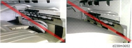
Junction gate/trailing edge presser mechanism

The junction gate motor [E] drives the junction gate [D], trailing edge presser [B], and the reverse rollers [C]. The junction gate motor HP sensor [A] detects the home position.
Timing of operation
Junction gate
![]()
Upper-transportation position Lower-transportation position
The junction gate moves to the lower transportation position when the trailing edge of the paper reaches the point 10mm after the junction gate. (Paper position is based on the entrance sensor, and is controlled by motor pulses.)
![]()
Lower-transportation position Upper-transportation position>
The junction gate moves to the upper transportation position when the trailing edge of the paper reaches the guide fence, and the trailing edge presser moves to the press position.
Trailing edge presser (Reverse roller)
![]()
Press position Pressure release position>
The trailing edge presser moves to the pressure release position when the trailing edge of the paper reaches the reverse roller.
![]()
Pressure release position Press position>
The trailing edge presser moves to the press position when the trailing edge of the paper reaches the guide fence.
The junction gate motor rotates clockwise, and switches the junction gate and the trailing edge presser (reverse roller). The positions of the junction gate, trailing edge presser and reverse roller vary as follows.
Figure | [A] Junction gate | [B] Trailing edge presser | [C] Reverse roller | |
Home | Upper | Pressur | Press | |
Position | transportatio | e | position | |
* | n position | release | ||
position | ||||
Position |
| Upper | Press | Pressur |
A | transportatio | position | e | |
n position | release | |||
position | ||||
Position |
| Lower | Press | Pressur |
B | transportatio | position | e | |
n position | release | |||
position | ||||
Position |
| Lower | Pressur | Press |
C | transportatio | e | position | |
n position | release | |||
position |
INTERNAL FINISHER SR3180 (D766)
The home position is at “Junction gate: Upper-transportation position” and “Trailing edge presser: Pressure release position”, and is detected by the junction gate motor HP sensor.
Sub-scan direction (transport direction) jogger mechanism
Paper transported to the stacking area by the paper exit rollers is delivered to the reverse rollers. Paper alignment for the sub-scan direction is performed by using the reverse rollers to press the trailing edge of the paper against the guide fence.
Paper detection on the stack guide plate
The paper exit sensor detects paper when there is paper on the stack guide plate.
Sheet edge face alignment mechanism (main-scan direction)


INTERNAL FINISHER SR3180 (D766)
This option does not have a jogger. Paper position adjustment for stapling (main-scan direction) is performed by paper shift and alignment of the paper edges using the registration sensor.
Paper transported to the shift rollers ([B] and [C]) is shifted when the trailing edge is 10mm from the paper exit roller. (Paper position is based on the entrance sensor, and is controlled by motor pulses.)
The paper shifts to a position where it can be detected by the sub-scan (leading edge) registration sensor [A]. The paper is then shifted for a specified distance. These operations are applied to each sheet, so that the edge of each sheet is aligned as shown by the blue line above.
Stapler mechanism
This option uses the crimping method. V-shaped teeth align the paper and press a tooth-mark onto the paper. This tooth-mark holds the paper together. The pressure applied is 220 kg.
This option performs two stapling movements for every stapling operation.
![]()
![]()
![]()
![]()

Moving to the first staple position Stapling Moving to the second staple position Stapling Moving back to the home position
The pressure cam [D] stretches the pressure link [A], and the upper tooth [C] and the lower tooth [B] fit into each other. Stapler movements and stapling operations are driven by the stapler drive motor. The stapler drive HP sensor detects the home position.
Double/Single Staple

It is difficult to adjust the bonding strength because it depends on how well the paper fibers twine. Setting to Single or Double allows you to adjust the bond strength.
For Single, stapling is applied twice.
For Double, after stapling is applied twice, the paper exit roller shifts the paper 4mm, and a stapling operation is applied again.
Paper exit
After stapling, the trailing edge presser is released. The paper exit rollers ejects the paper.
INTERNAL FINISHER SR3180 (D766)
Stapler movement mechanism
Because this stapler needs to staple twice for a single staple position, there is a mechanism to move the stapler.
The grooved cam [A] inside the stapler unit rotates, and the securing pin passes over the grooves to guide the cam.
Stapler movements and stapling operations are driven by the stapler drive motor [B]. The stapler home position sensor [C] detects the home position.
R EVI SIO N HIS TORY | ||
Page | Date | Added/ Updated/ New |
None | ||
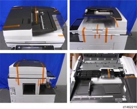
DOCUMENT FEEDER 1
ORIGINAL FEED UNIT 1
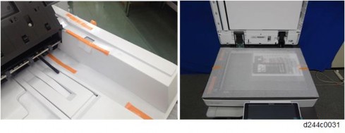
EXTERIOR COVERS AND ORIGINAL TRAY 2
REAR COVER 2
FRONT COVER AND ORIGINAL TRAY 3
SENSORS AND SWITCH 4
ORIGINAL LENGTH SENSORS AND ORIGINAL SENSOR 4
ORIGINAL SET SENSOR 5
ORIGINAL WIDTH SENSORS AND SKEW CORRECTION SENSOR 7
ORIGINAL EXIT SENSOR 7
REGISTRATION SENSOR 9
DF POSITION SENSOR 9
LEFT COVER SWITCH 10
MOTORS, SOLENOIDS, AND CLUTCHES 11
FEED MOTOR 11
TRANSPORT MOTOR 13
STAMP SOLENOID 14
PICK-UP SOLENOID 16
INVERTER SOLENOID 16
FEED CLUTCH 17
BELT AND ROLLERS 18
FEED BELT 18
PICK-UP ROLLER 19
SEPARATION ROLLER 20
BOARD 21
ARDF DRIVE BOARD 21
2.1 ARDF DF3090 (D779) 22
PARTS LAYOUT 22
MECHANISM 24
SM i D779
Original Detection 24
Original Size Detection / Original Set Detection Mechanism 24
Paper Feed / Separation Mechanism 26
Skew Correction Mechanism / Registration Mechanism 27
SP6-901-002 (SETTING TO GIVE PRIORITY TO STACKABILITY) 30
This manual uses several symbols and abbreviations. The meaning of those symbols and abbreviations are as follows:
| Clip ring |
| Screw |
| Connector |
| Clamp |
| Timing belt |
SEF | Short Edge Feed |
LEF | Long Edge Feed |

Short Edge Feed (SEF)
Long Edge Feed (LEF)
Microsoft®, Windows®, and MS-DOS® are registered trademarks of Microsoft Corporation in the United States and /or other countries.
PostScript® is a registered trademark of Adobe Systems, Incorporated.
PCL® is a registered trademark of Hewlett-Packard Company. Ethernet® is a registered trademark of Xerox Corporation.
PowerPC® is a registered trademark of International Business Machines Corporation.
Other product names used herein are for identification purposes only and may be trademarks of their respective companies. We disclaim any and all rights involved with those marks.
ARDF DF3090 (D779)
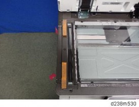
Open the left cover.
Original feed unit [A]
Pull the original feed unit forward to release the back side of the shaft.
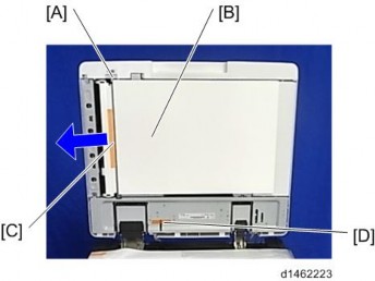
Open the left cover [A].
Open the original tray [B].
Rear cover [C] ![]() ×1, hook ×5)
×1, hook ×5)

ARDF DF3090 (D779)
Open the left cover.
Rear cover (page 2)
Front cover [A] ![]() ×1)
×1)
Keep the original tray open when removing the front cover.
Original tray [A] ![]() ×1,
×1, ![]() ×1,
×1, ![]() ×1)
×1)
Original Tray (page 3)
Tray cover [A] ![]() ×3)
×3)
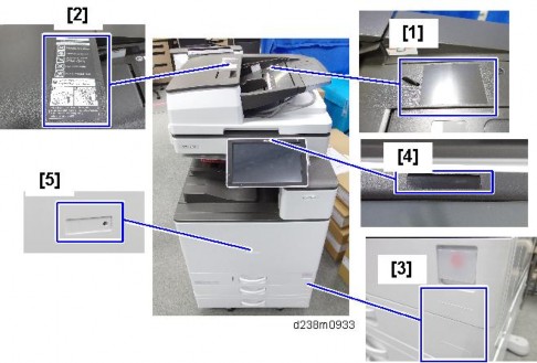
Remove the following items:
Original sensor [A] ![]() ×1)
×1)
Original length sensors [B] ![]() ×1 each)
×1 each)
ARDF DF3090 (D779)
Original feed unit (page 1)
Original tray (page 3)
Original feed-in guide plate [A] ![]() ×3)
×3)
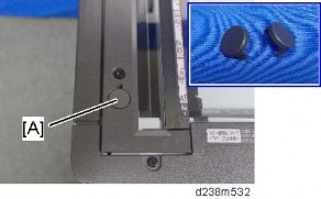
Feed guide [A]

Original turn guide plate [A] (hook ×2)

Original set sensor bracket [A] (hook ×2)
Original set sensor [A] ![]() ×1)
×1)
ARDF DF3090 (D779)
Original turn guide plate (page 5)
Original width sensors [A] ![]() ×1 each) and skew correction sensor [B] with bracket
×1 each) and skew correction sensor [B] with bracket ![]() ×1,
×1, ![]() ×1)
×1)
Original feed-in guide plate (page 5)
The Original exit sensor [A] is located in the ARDF mainframe.
Original exit sensor bracket [A] ![]() ×1)
×1)
Original exit sensor [A] ![]() ×1)
×1)
ARDF DF3090 (D779)
Original feed-in guide plate (page 5)
Registration sensor [A] ![]() ×1)
×1)
ARDF Drive Board (page 21)
DF position sensor with bracket [A] ![]() ×1)
×1)
DF position sensor [A] ![]() ×1)
×1)
Rear cover (page 2)
Left cover switch [A] ![]() ×2,
×2, ![]() ×2)
×2)
ARDF DF3090 (D779)
Rear cover (page 2)
Feed motor harness [A] ![]() ×1)
×1)

Harness guide [A] ![]() ×5)
×5)
Feed motor with bracket [A] ![]() ×2, spring [B]×1,
×2, spring [B]×1, ![]() ×1)
×1)
Feed motor [A] ![]() ×2)
×2)

ARDF DF3090 (D779)
Rear cover (page 2)
Transport motor bracket [A] (spring ×1, ![]() ×2,
×2, ![]() ×1)
×1)
Transport motor [A] ![]() ×2)
×2)
Rear cover (page 2)
Stamp solenoid harness [A] ![]() ×1,
×1, ![]() ×1)
×1)
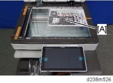
Open the DF and remove the platen sheet [A].
Stamp solenoid cover [A] ![]() ×1)
×1)
ARDF DF3090 (D779)
Stamp solenoid [A] ![]() ×1)
×1)
Pull out the harness [A].
Rear cover (page 2)
Harness guide (page 11)
Pick-up solenoid [B] ![]() ×2,
×2, ![]() ×1)
×1)

Rear cover (page 2)
Harness guide (page 11)
Inverter solenoid [A] ![]() ×2,
×2, ![]() ×1,
×1, ![]() ×1, gear ×1, gear cover ×1,
×1, gear ×1, gear cover ×1, ![]() ×1)
×1)

ARDF DF3090 (D779)
Rear cover (page 2)
Original feed unit (page 1)
Feed clutch [A] ![]() ×2, bushing ×1, shaft ×1,
×2, bushing ×1, shaft ×1, ![]() ×1,
×1, ![]() ×1)
×1)
Original feed unit (page 1)
Feed belt cover [A] (spring×1)

When reattaching the feed belt cover, make sure that the projection [B] of the feed belt cover is on the guide plate rear [C].
Belt tension unit [D]

ARDF DF3090 (D779)
Feed belt [E]

Original feed unit (page 1)
Pick-up roller [A] ![]() ×1)
×1)
Original Feed Unit (page 1)
Separation roller cover [A]
Separation roller [A] ( ×1)
3.
ARDF DF3090 (D779)
Rear cover (page 2)
ARDF drive board [A] ![]() ×2,
×2, ![]() ×7)
×7)


No. | Description | No. | Description |
1 | Original Width Sensor 5 (LL) | 13 | Original Length Sensor (M) |
2 | Original Width Sensor 4 (L) | 14 | Original Length Sensor (L) |
3 | Original Width Sensor 3 (M) | 15 | DF Position Sensor |
4 | Original Width Sensor 2 (S) | 16 | Transport Motor |
No. | Description | No. | Description |
5 | Original Width Sensor 1 (SS) | 17 | Feed Clutch |
6 | Skew Correction Sensor | 18 | Cooling Fan Motor |
7 | Registration Sensor | 19 | Cover Switch |
8 | Original Exit Sensor | 20 | Pick-up Solenoid |
9 | Original Set Sensor | 21 | Feed Motor |
10 | Stamp Solenoid | 22 | Inverter Solenoid |
11 | Original Sensor | 23 | ARDF Drive Board |
12 | Original Length Sensor (S) | - | - |
ARDF DF3090 (D779)
Original Detection
When an original is placed on the original tray correctly, the edge of the original pushes up the feeler of the original sensor.
Original Size Detection / Original Set Detection Mechanism
Five original width sensors detect the width of the original just when the leading edge of the original passes the interval sensor. Three original length sensors on the original table detect the length. These two pieces of size information summarize the original size.
Size (Width x Length: mm) | Width Detection | Length Detection | |||||||
1 | 2 | 3 | 4 | 5 | S | M | L | ||
1 | A3 SEF (297 x 420) | On | On | On | On | On | On | On | On |
2 | B4 SEF (257 x 364) | On | On | On | - | - | On | On | On |
3 | A4 SEF (210 x 297) | On | On | - | - | - | On | On | - |
4 | A4 LEF (297 x 210) | On | On | On | On | On | - | - | - |
5 | B5 SEF (182 x 257) | On | - | - | - | - | On | - | |
6 | B5 LEF (257 x 182) | On | On | On | - | - | - | ||
7 | A5 SEF (148 x 210) | On | - | - | - | - | - | ||
8 | A5 LEF (210 x 148) | On | On | - | - | - | - | ||
9 | B6 SEF (128 x 182) | - | - | - | - | - | - | ||
10 | B6 LEF (182 x 128) | On | - | - | - | - | - | - | - |
11 | 11" x 17" SEF (DLT) | On | On | On | On | - | On | On | On* |
12 | 11" x 15" SEF | On | On | On | On | - | On | On | On * |
13 | 8 1/2" x 11" SEF (LT) | On | On | - | - | - | On | - | - |
14 | 11" x 81/2" LEF (LT) | On | On | On | On | - | - | - | - |
The machine cannot tell the difference between certain original sizes, such as DLT (11 x 17”) and 11 x 15”. The machine assumes such originals are 11 x 17”. To change this, use SP mode.
ARDF DF3090 (D779)
Sensor Position
Description | |
A | Original Width Sensors |
B | Original Set Sensor |
C | Original Length Sensors |
Paper Feed / Separation Mechanism
The separation mechanism uses the RF method.
When the originals are placed and [Start] is pressed, the paper feed solenoid is turned ON and the pickup roller [A] goes down to the original. At this time, the paper feed motor [B] switches on and the pickup roller and paper feed motor [B] start rotating. Then a sheet of paper is fed.

Description | |
A | Pickup Roller |
B | Paper Feed Motor |
C | Paper Feed Belt |
ARDF DF3090 (D779)
Skew Correction Mechanism / Registration Mechanism
Skew Correction
This machine adjusts paper skew by hitting the originals against the pullout roller [A].
The skew correction sensor [B] detects the leading edge of the original after it passes through the separation area. When the leading edge reaches the entrance transport roller, the paper is fed a bit more so that it bumps into the pullout roller [A], to make slack for skew adjustment.
Registration Mechanism

The registration sensor [C] detects the leading edge of the originals. The machine uses the data for registration during copying.
A | Pullout Roller |
B | Skew Correction Sensor |
C | Registration Sensor |
D | Original Width Sensor |
E | Sheet-through Exposure Glass |
Transport Mechanism (Simplex)
Originals are transported by the pullout roller [A] and the entrance transport roller [B] to the sheet-through exposure glass [E], which scans the image. After this process, the originals are transported to paper exit section by the exit transport roller [D] and the exit driven roller [E].

Description | |
A | Pullout Roller |
B | Entrance Transport Roller |
C | Sheet-through Exposure Glass |
D | Exit Transport Roller |
E | Exit Driven roller |
Transport Mechanism (Duplex)
When originals are detected by the skew correction sensor [A], the transport motor switches OFF and the original stops for a while. After skew correction, the originals are re-transported to the sheet-through exposure glass [B], which scans the first side (front). Then the inverter solenoid switches ON and the junction gate [C] opens. By that process, the originals are transported to the reverse roller. At this time, the transport motor stops and the inverter solenoid switches off.
Description | |
A | Skew Correction Sensor |
B | Sheet-through Exposure Glass |
C | Junction Gate |
ARDF DF3090 (D779)
The originals, which reached the reverse roller, are re-fed over the upper surface of the junction gate [A]. When the originals reach the sheet-through exposure glass [B], the second side (back) is scanned.
To make the order of the sheets on the exit tray correct, the two sides (front/back) of the original need to be inverted. Therefore, the inverter solenoid switches ON and the originals are transported to the reverse roller again. After the inversion, the originals exit onto the exit tray [C].


