
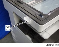
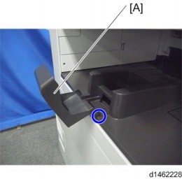
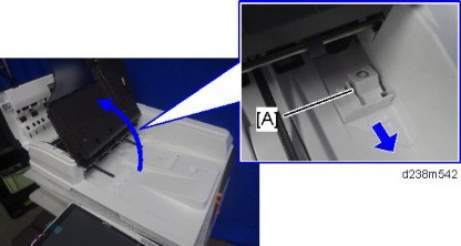
Open the right door, and then remove the small cover [A].
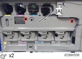
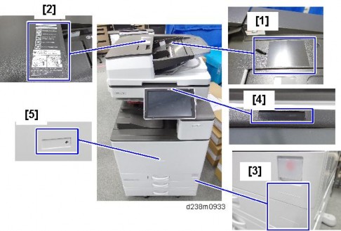
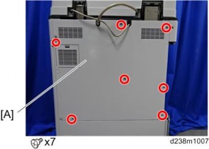
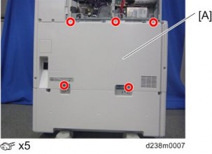
Remove the screw and connector, and then remove the front upper cover [A].

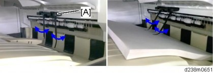
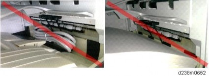
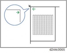
Remember that there are three tabs at the positions in the red arrows.
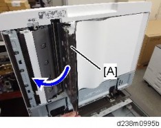
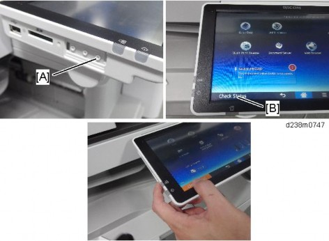
Tilt the operation panel [B] upward to a horizontal position, and then remove the front upper cover [A].

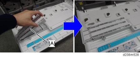
Remove the paper exit cover [A] ![]() ×1).
×1).

Remove the connector cover [A].

Remove the paper exit lower cover [A].

Remove the upper rear inner cover [A] ![]() ×2)
×2)

Install a screw removed in step 12.

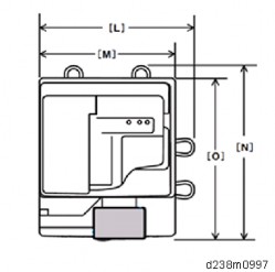
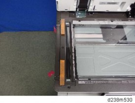
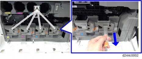
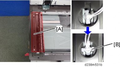
While pressing the bottom plate [A] into the area shown by the blue circle [B], insert it into the slot shown by the blue circles [C] [D].
The following procedure is the easiest way to set this component.
Slip the bottom plate [A] into the position in the blue circle [B].
Insert the bottom plate [A] into the hole in the blue circle [C].
When the bottom plate [A] is picked up (see below), it can be inserted into the hole in the blue circle [D].

Attach the bottom plate [A] ![]() ×3)
×3)

Attach the upper rear inner cover.
Attach the paper exit cover.
Reattach the connector cover, front upper cover, and then close the right door.
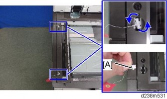
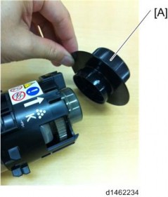
Remove the driven roller [B] at the machine’s exit tray and attach the supplied driven roller [A].
Insert a flathead screwdriver into the depression in the center, and then, lifting the driven roller, unlock the part indicated by the red arrow.
When attaching the driven roller, push its center all the way in until it clicks.
[A]: The supplied driven roller has flat rollers.
[B]: The machine’s standard driven roller has drum-type rollers (as indicated by red frames).
Attach the paper support guide [A] (Tab x4).

Up to this point, the procedure is the same as punch unit installation (for fitting the punch unit, refer to Step 3 and later of the Punch unit installation procedure).
Slide the finisher front right cover [A] from left to right to attach it ![]() ×1).
×1).

Reattach the inverter tray.
Attach the entrance guide plate [B] to the finisher [A] ![]() ×2).
×2).

Slide the finisher [A] along the rail of the bottom plate from the left-hand side of the machine to attach it ![]() ×1).
×1).

Hold the front side [A] of the internal finisher as shown below to check if the internal finisher is correctly set in the rail of the bottom plate.

Reattach the left rear cover.
Insert the upper left cover [A] from the front, and slide it to reattach it.

Attach the stabilizers.
Because the weight is biased to the right of the machine if the internal finisher is installed, stabilizers are required on the left side. Because they are included with the finisher, install these stabilizers at the same time as you install the internal finisher.

Remove the connector cover, then connect the interface cable to the machine.

Move the stapler unit forward, then set the staple cartridge [A].

Reinstall the stapler unit, and then turn ON the main power.
Check that the finisher can be selected at the operation panel, and check the finisher operation. Also when the punch unit is installed, check the punching operation.
Punching unit for the Internal Finisher SR3130 (D690).
No. | Description | Q’ty | Remarks |
1 | Hopper | 1 | |
2 | Punch Unit Cover | 1 | |
3 | Lower Front Cover | 1 | |
4 | Lower Rear Cover | 1 | |
5 | Holder | 1 | |
- | Knob Screw - M4 | 1 | |
- | Tapping screws - M3x 6 | 3 | |
- | Decal - EMC Address | 1 |

When installing this option, turn OFF the main power and unplug the power cord from the wall socket. If installing without turning OFF the main power, an electric shock or a malfunction may occur.
When supplied together with the "Internal Finisher SR3130", attach this option before installing the "Internal Finisher SR3130"
If the "Internal Finisher SR3130" is already attached, attach this option after removing the finisher.
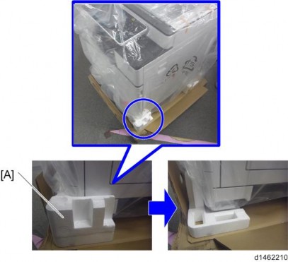
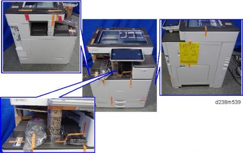
Take out from the box, and remove the filament tape and packing material.
Remove the finisher and finisher front right cover from the machine.
Perform steps 1 to 21 of the installation procedure for the "Internal finisher SR3130".page 2-144 "Internal Finisher SR3130 (D690)"
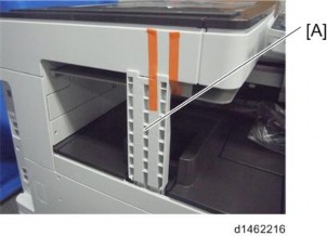
Change the fixing position of the bracket [A] of the bottom plate ![]() ×1).
×1).

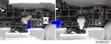
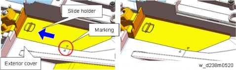
Replace the lock holder of the bottom plate with the lock holder [A] ![]() ×1) provided with the accessories.
×1) provided with the accessories.

Reattach the front upper cover.
Pass the shafts [B] of the punch unit [A] through the bearings [C] of the bottom plate, and attach to the machine ![]() ×1, knob screw).
×1, knob screw).
If it is difficult to insert by probing, look from the side while you insert it into the bearings of the bottom plate.


When installing the punch unit in a finisher that is already installed, remove the relay guide plate [A] ![]() ×2).
×2).
This step is unnecessary when installing the finisher and punch unit at the same time.

Attach the punch unit cover [A] provided with the accessories, inserting the tabs ![]() ×1).
×1).
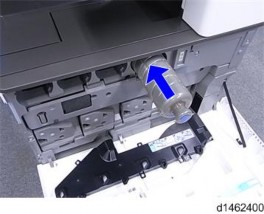
Insert the hopper [A].

Slide the finisher [A] along the rail of the bottom plate from the left-hand side of the machine to attach it ![]() ×1).
×1).

Attach the components [A] and [B] to the finisher ![]() ×2).
×2).

Attach the left rear cover.
Insert the upper left cover [A] from the front, and slide it to attach it.
Attach stabilizers.
Because the weight is biased to the right of the machine if the internal finisher is installed, stabilizers are required on the left side. Because they are included with the finisher, install these stabilizers at the same time as you install the internal finisher.

Remove the connector cover, then connect the interface cable to the machine.
Move the stapler unit forward, then set the stapler [A].

Turn ON the main power.
Check that the finisher can be selected at the operation panel, and check the finisher and punch operation.
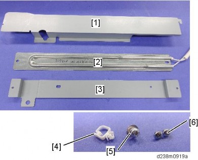
No. | Description | Q’ty | Remarks |
1 | Bottom Plate | 1 | |
2 | Left Lower Cover | 1 | |
3 | Paper Exit Tray | 1 | |
4 | TAPPING SCREW:3x8 | 2 | |
5 | TAPPING SCREW:3x8 | 2 | |
6 | TAPPING SCREW:3x8 | 2 | |
7 | SCREW:M3x6 | 3 | |
8 | TAPPING SCREW:3x6 | 1 | |
9 | TAPPING SCREW:4x8 | 1 | |
10 | Slide Rail | 1 | |
11 | Nylon Clamp | 1 | |
12 | Paper Support Guide | 1 | |
13 | Driven Roller (Flat) | 1 |

When installing this option, turn OFF the main power and unplug the power cord from the wall socket. If installing without turning OFF the main power, an electric shock or a malfunction may occur.
This option cannot be used together with the following peripherals:
Internal Shift Tray SH3070 (D691)
Side Tray Type M3 (D725)
Internal Finisher SR 3130 (D690)
Bridge Unit BU3070 (D685)
For using this option together with "1 Bin Tray BN3110 (D3CQ)", attach the bottom plate of this option at the beginning, then install the "1 Bin Tray BN3110 (D3CQ)", followed by installing this option.
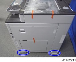
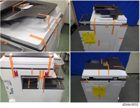
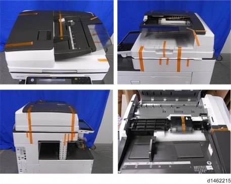
Remove the orange tapes and shipping retainers.

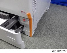
Remove the knob screw and red tag [A].

Remove the shaft [B] from the slide rail [A] ![]() x 1).
x 1).

Remove the paper exit cover [A] ![]() x 2).
x 2).
Place the slide rail [A] under the internal finisher [B].

Insert the shaft [A] into the holes located in the slide rail and internal finisher, and then
fasten with the screw ![]() x 1).
x 1).
Attach the paper exit cover (removed in step 4) [A] ![]() x 2).
x 2).
Remove the paper exit tray [A].

Remove the paper exit feeler [A].

Open the front cover, and then remove the left upper cover [A] ![]() x 1).
x 1).
Remove the left rear cover [A] ( x 2).
Remove the inverter tray [A] and tray support plate [B].
Open the right door, and then remove the small cover [A].

Remove the screw and connector, and then remove the front upper cover [A].
Remember that there are three tabs at the positions of the red arrows.
Tilt the operation panel [B] upward to a horizontal position, and then remove the front upper cover [A].
Remove the paper exit cover [A] ![]() x 1).
x 1).
Remove the connector cover [A].
Remove the paper exit lower cover [A].
The lower inside cover can be removed together with the paper exit lower cover, since the inside cover is secured on the paper exit lower cover with two screws.

Remove the lower inside cover [B] from the paper exit lower cover [A] ![]() x 2).
x 2).
Remove the upper inside cover [A] ![]() x 2).
x 2).
Insert the bottom plate [A] into the holes.
Install the bottom plate [A] ![]() x 3, Accessory No. 7).
x 3, Accessory No. 7).

Install the lower inside cover (removed in step 18) [A] in the finisher ![]() x 2, Accessory No.5).
x 2, Accessory No.5).
Reattach the upper inside cover (removed in step 19) [A] ![]() x 2).
x 2).
Reattach the tray support plate (removed in step 12) [A].
Reattach the paper exit cover (removed in step 15 and step 16) [A] and the connector cover [B].

Touching the moving parts inside of the cover can result in an injury. To avoid this, be sure to install the connector cover [B].
Reattach the front upper cover (removed in step 14) and then close the right door.
Remove the driven roller [B] at the machine’s exit tray and attach the supplied driven roller [A].
Insert a flathead screwdriver into the depression in the center, and then, lifting the driven roller, unlock the part indicated by the red arrow.
When attaching the driven roller, push its center all the way in until it clicks.
[A]: The supplied driven roller has flat rollers.
[B]: The machine’s standard driven roller has drum-type rollers (as indicated by red frames).
Attach the paper support guide [A] (Tab x 4).

Install the internal finisher [A].
Secure the finisher ![]() x 1, Accessory No.8).
x 1, Accessory No.8).

Reattach the left rear cover [A]
Reattach the left upper cover [A].
Attach the left lower cover [A] ![]() x 2, Accessory No.6).
x 2, Accessory No.6).
Attach the paper exit tray [A] ![]() x 2, Accessory No.4).
x 2, Accessory No.4).

Reattach the inverter tray [A] removed in step 12.
Remove the connector cover [A] (Release the tab).

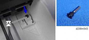
Connect the interface cable [A].

Attach the nylon clamp [A] as shown below ![]() x 1, Accessory No.9).
x 1, Accessory No.9).
Turn ON the main power.
Ensure that the operation panel displays finisher jobs properly and that it works properly.
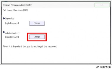
To adjust the strength of the crimp between sheets of stapled paper, there is a setting to select either single or double stapling.
The crimp is weakened when there is an image (toner) at the point which is to be stapled. There also is a setting to mask the image on the point for stapling, in order to prevent the crimp from being weakened.
Depending on users demands, explain the settings/methods of the settings by checking the following instructions.
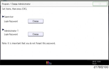
Use this procedure to select the type of stapling that is done by the stapleless stapler.
Note that if you change the finisher type from Finisher SR3210 to Internal Finisher SR3180, which has the same type of stapleless staple unit, the current setting in [Stapling Method for Stapleless Stapler] is not carried over, so configure the setting again.
Press the [User Tools] icon on Home screen.
Press [Machine Features] > [System Setting] > [General Setting] >[Stapling Method for Stapleless Stapler].
Select [Double] or [Single].
Press the [User Tools] icon.
Press [Machine Features] > [System Setting] > [General Setting].
Press [Erase Margin for Stapleless Stapler].
No. | Description | Q’ty | Remarks |
1 | Main Tray | 1 | |
2 | Lock Plate | 1 | |
3 | Sub Tray | 1 | |
4 | Rivet | 2 |
When installing this option, turn OFF the main power and unplug the power cord from the wall socket. If installing without turning OFF the main power, an electric shock or a malfunction may occur.
Be careful not to get your finger caught in the area indicated by the red frame (the tray’s rotating and insertion part).
Open the bypass tray, and then attach the sub tray [A]. (Rivet x2)
Fold the sub-tray.
While pressing down the feeler [B] on the bypass tray, push the main tray [A] into the bypass tray to attach it.
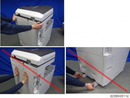
When you attach the tray, hold it with both hands to make sure that it does not fall.
Check if the locks on the main tray’s sides are engaged.
Attach the belt by engaging it with the hooks [A].

Remove the backing paper for the double-sided tapes on the lock plate.

Stick the lock plate [B] with its center aligned with the indentation [A] on the right door.
Tuck in the banner paper guide tray [A].

The double-sided adhesive tapes stick firmly in about one day.
When replacing the parts of the Banner Paper Guide Tray, use the installation procedure above in reverse order as a reference in order to make it easier to disassemble the unit.
No. | Description | Q’ty | Remarks |
1 | Paper transfer roller (Extended) | 1 |
When installing this option, turn OFF the main power and unplug the power cord from the wall socket. If installing without turning OFF the main power, an electric shock or a malfunction may occur.
Do not touch the roller surface during replacement. Also, when taking out the unit from the box, be careful not to touch the roller surface [A].

Enter the SP mode.
Set SP2-400-001(Paper Transfer Roller Settings Width of Paper Transfer Roller) to "1”.
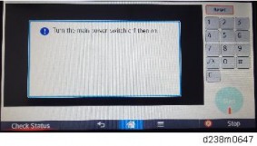
When SP2-400-001 is changed over, a message is displayed stating "Switch the power OFF/ON".
After the SP is changed, turn OFF the main power.
Replace the roller [A].
For details about how to replace the roller, refer to page 4-86 "
Paper Transfer Roller".
During PM replacement, do not install the wrong type of roller.

[A]: The standard roller has a gray collar at its end.
[B]: Imageable Area Extension Unit Type M19 does not have a collar on it.
Turn ON the main power.
Using SRA3 paper, check that a full-bleed halftone image is output, and that the image extends to 315 mm in width.
SP descriptions
SP2-400-001 (Paper Transfer Roller Settings)
Specifies the width of the Paper Transfer Roller. This SP must be set to "1" when Imageable Area Extension Unit Type M19 is installed.
0: Default roller
1: Wide roller
The following problems occur.
When a change-over was made from a standard roller to the imaging range extension option
(If the SP setting is the normal setting (SRA3 paper not supported), but the optional longer paper transfer roller is installed)
The image cannot be correctly transferred to the SRA3 paper area.
The MUSIC/program control pattern adheres to the ends of the paper transfer roller (outside the A3 area), and this can transfer to the underside of printouts.
Real-time process control cannot be performed correctly, and an abnormal image and SC285-00 (MUSIC error) may occur.
When a change-over was made from the imaging range extension option to a standard roller
(If the SP setting is for SRA3, but the paper transfer roller is the normal one (SRA3 paper not supported))
Real-time process control is not performed, and the interval between process controls becomes short.
The waiting time for fusing temperature rise is longer than intended.
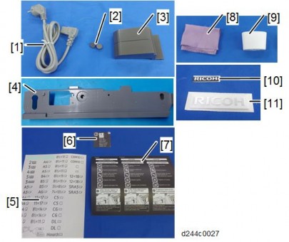
No. | Description | Q’ty | Remarks |
1 | Keyboard table bracket | 1 | |
2 | Keyboard stand bracket | 1 | |
3 | Keyboard stand | 2 | |
4 | Screw: M4 x 12 | 2 | |
5 | Screw: M3 x 8 | 4 | |
6 | Screw: M3 x 12 | 1 |
This optional unit is not supplied with a keyboard. Use a commercially available keyboard.
When installing this option, turn OFF the main power and unplug the power cord from the wall socket. If installing without turning OFF the main power, an electric shock or a malfunction may occur.
Open the right door, and then remove the small cover [A].

Remove the screw and connector, and then remove the front upper cover [A].

Remember that there is a tab at the positions of the red arrows.
Rotate the operation panel [B] upward to a horizontal position, and then detach the front upper cover [A].
Remove the screw [A] on the frame of the machine.
Make 3 screw holes in the front upper cover.

Reattach the front upper cover to the machine.
Attach the keyboard stand bracket [A] on the front upper cover ![]() x3).
x3).

Attach the keyboard stand [A] on the keyboard stand bracket ![]() x4).
x4).

Place a keyboard on the keyboard stand, and then pass the keyboard cable through the hole in the keyboard stand.
Remove the rear cover [A].
Remove the scanner right cover [A] ![]() ×1)
×1)
Route the keyboard cable [A] along the right side of the scanner unit as shown below.
Route the keyboard cable along the rear side of the scanner unit ![]() x1).
x1).
Adjust the keyboard cable by making loops if the keyboard cable has too much slack.

Remove the cutout [A] in the left rear cover to make a cable hole, and then pass the keyboard cable [B] through it.
Connect the keyboard cable to the USB slot.
Reattach the scanner right cover, and rear cover.
Close the right door.
Slot | Option | |
[A] | USB mini | Used for the PictBridge function. |
[B] | USB port*2 |
|
[C] | I/F slot |
|
[D] | I/F slot*1 | Fax Option Type M19 (D3BV-01) |
*1 Dedicated slot for fax unit
*2 There is no difference between the left and right USB port.
No | Items | Q’ty | Remarks |
1 | USB Cable | 1 | |
2 | Interface Board | 1 | |
3 | Ferrite Core | 2 | |
4 | Cable Ties | 2 |
An Ethernet cable is not packed with this option.
No. | Item | Description |
1 | Switch | Used to reset to the factory settings. |
2 | Ethernet port | Used to connect the Ethernet cable. |
3 | USB port | Used to connect this option to the main machine. Do not use this port with other options. |
When installing the USB device server option, make sure that the labels 'USB-A' and 'Ethernet' are upside down.
When installing this option, turn OFF the main power and unplug the power cord from the wall socket. If installing without turning OFF the main power, an electric shock or a malfunction may occur.
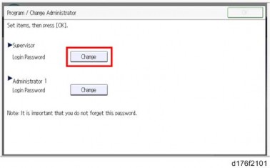
The USB device server option has an IP address stored on the PCB. This is different from the machine's IP address. The IP address and other network settings of the USB device server option must be configured after installing this option.
Turn OFF the main power of the machine, and unplug the power cord from the wall socket.
Remove the slot cover [A].

Insert the interface board [A] into the I/F slot.

Remove the I/F cover [A].
Cut off the USB port cover [A] with nippers or other such tool.
Reattach the I/F cover.
Insert the USB cable [A] into the USB port (Type A) on the machine I/F.
Insert the other side of the USB cable [B] into the USB port (Type B) on this option board.

Attach the ferrite cores to the Ethernet cable, while looping the cable at 3 cm (approx.
1.2 inch) [A] from the each end of the cable.

Only for installing this option in North America, bind both cores with cable ties [A] as shown below.
The two binds are not included in options produced before March, 2015. To bind the cores, use the binds registered as service parts or similar ones.