PUNCH UNIT PU3040 (D716)
Horizontal registration sensor unit (page 13).
Horizontal registration sensor unit motor [A] ![]() ×2,
×2, ![]() ×1)
×1)

Horizontal registration sensor unit (page 13).
Punch hopper full sensor unit [A] ![]() ×1)
×1)
Punch hopper full sensor [A] ( ×1)
3.

PUNCH UNIT PU3040 (D716)
Horizontal registration sensor unit (page 13).
Horizontal registration unit bracket [A] ![]() ×2)
×2)

Horizontal registration sensor [A] ![]() ×1)
×1)


No. | Description | No. | Description |
1 | Punch unit home position sensor | 4 | Punch hopper |
2 | Punch unit | 5 | Punch unit motor |
3 | Horizontal registration sensor unit |
PUNCH UNIT PU3040 (D716)
No. | Description | No. | Description |
1 | Punch unit pulse sensor | 6 | Horizontal registration sensor unit motor |
2 | Punch unit motor | 7 | Horizontal registration sensor unit home position sensor |
3 | Horizontal registration sensor | 8 | Punch hopper full sensor |
4 | Horizontal registration transport unit motor | 9 | Punch unit controller board |
5 | Horizontal registration transport unit home position sensor |
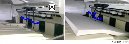
Transport mechanism
Paper from the main machine passes through the horizontal registration sensor unit, and is transported to the punch unit and the entrance of the finisher.

No. | Description | No. | Description |
1 | Finisher paper entrance | 3 | Horizontal registration sensor unit |
2 | Punch unit |
Horizontal registration transport unit mechanism
When the entrance sensor of the finisher detects the leading edge of the paper, the horizontal registration transport unit motor rotates to measure the horizontal registration of the paper. The horizontal registration sensor unit home position sensor detects the home position.
PUNCH UNIT PU3040 (D716)
Horizontal registration sensor unit mechanism

The horizontal registration sensor unit has a horizontal registration sensor, which detects the horizontal registration (offset) of the paper relative to the punch unit position.
No. | Description | No. | Description |
1 | Horizontal registration sensor | 3 | Horizontal registration sensor unit home position sensor |
2 | Horizontal registration sensor unit motor |
Punch unit mechanism
The punch unit moves according to information from the horizontal registration sensor, so that punch holes can be made in the correct positions. The punch unit is moved by the horizontal registration transport unit motor. The horizontal registration transport unit home position sensor detects the home position.

No. | Description | No. | Description |
1 | Horizontal registration transport unit home position sensor | 2 | Horizontal registration transport unit motor |
Punch mechanism
The punch unit motor rotates to move the links via gears. This moves the punch pin up and down. After punching, punch waste is collected in the punch hopper under the unit. The hopper has a punch hopper full sensor so that punch waste does not overflow. Because the punch motor is a DC motor, the motor shaft has an encoder, and there is a punch unit motor pulse sensor. The punch unit also has a mechanism for changing the punch positions according to the country/region of installation.

No. | Description | No. | Description |
1 | Links | 5 | Punching position sensor |
2 | Punch pin | 6 | Punch hopper |
3 | Punch motor unit pulse sensor | 7 | Punch hopper full sensor |
4 | Punch motor |
PUNCH UNIT PU3040 (D716)
Punching position changing mechanism
The punch unit also has a mechanism for changing the punch positions according to the country/region of installation.
Japan: 2 holes
North America: 2/3 holes
Europe: 2/4 holes
Northern Europe: 4 holes
The punching position sensor detects a change in the punching position.
holes
The position where the 1st drive gear has not moved is the 2-hole home position. The 1st drive gear rotates clockwise/anti-clockwise, and only one link is moved, and this moves the necessary punch pins.
or 4 holes
The position where the 1st drive gear has rotated forward by 180° is the 3 or 4-hole home position. The 1st drive gear rotates clockwise/anti-clockwise, and the two links are moved, and these move the necessary punch pins.

No. | Description | No. | Description |
1 | Punch pin | 4 | Punching position sensor |
2 | 2-hole link | 5 | 3/4-hole link |
3 | 1st drive gear |
R EVI SIO N HIS TORY | ||
Page | Date | Added/ Updated/ New |
None | ||
SIDE TRAY MOTOR UNIT 1
PAPER EXIT SENSOR 4
SIDE TRAY PAPER EXIT SENSOR 7
PAPER EXIT TRAY SET SWITCH 8
PAPER EXIT SWITCHING UNIT SET SWITCH 9
SIDE TRAY TYPE M3 (D725) 10
PARTS LAYOUT 10
MECHANISM 12
Drive Mechanism 12
Paper Transport Mechanism 12
This manual uses several symbols and abbreviations. The meaning of those symbols and abbreviations are as follows:
| Clip ring |
| Screw |
| Connector |
| Clamp |
SEF | Short Edge Feed |
LEF | Long Edge Feed |

Short Edge Feed (SEF)
Long Edge Feed (LEF)
Microsoft®, Windows®, and MS-DOS® are registered trademarks of Microsoft Corporation in the United States and /or other countries.
PostScript® is a registered trademark of Adobe Systems, Incorporated.
PCL® is a registered trademark of Hewlett-Packard Company. Ethernet® is a registered trademark of Xerox Corporation.
PowerPC® is a registered trademark of International Business Machines Corporation.
Other product names used herein are for identification purposes only and may be trademarks of their respective companies. We disclaim any and all rights involved with those marks.
SIDE TRAY TYPE M3 (D725)
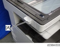
Upper extension tray [A], Left extension tray [B].

Fixing plate [A] ![]() ×1).
×1).

Side tray [A] ![]() ×1).
×1).

Side tray motor unit cover [A] ![]() ×2).
×2).

Side tray rear cover [A] ![]() ×1).
×1).

SIDE TRAY TYPE M3 (D725)
Side tray motor unit [A] ![]() ×3,
×3,![]() ×2).
×2).

Side tray (page 1).
Paper exit tray [A].

Side tray motor unit cover (page 1).
Side tray rear cover (page 1).
Side tray paper exit cover [A] ![]() ×1).
×1).

SIDE TRAY TYPE M3 (D725)
Paper exit switching unit [A] ![]() ×1,
×1, ![]() ×1,
×1, ![]() ×1).
×1).

Paper exit switching unit cover [A] ![]() ×4).
×4).

Guide plate [A].
Guide plate [A] ![]() ×1).
×1).
Paper exit sensor [A] ![]() ×1).
×1).

Paper exit tray (page 4).
SIDE TRAY TYPE M3 (D725)
Place the unit upside down.
Side tray paper exit sensor [A] ![]() ×1).
×1).

Paper exit tray (page 4)
Paper exit set switch cover [A]
Paper exit tray set switch [A] ![]() ×1)
×1)

Open the paper exit switching unit [A].
SIDE TRAY TYPE M3 (D725)
Paper exit switching unit switch cover [A]
Paper exit switching unit set switch [A] ![]() ×1)
×1)

No. | Description | No. | Description |
1 | Paper exit roller | 6 | Side tray paper exit sensor |
2 | Paper exit sensor | 7 | Transport roller 2 |
3 | Paper junction gate | 8 | Transport roller 3 |
4 | Paper exit switching unit set switch | 9 | Paper exit tray set switch |
5 | Transport roller 1 |
SIDE TRAY TYPE M3 (D725)

No. | Description | No. | Description |
1 | Side tray motor | 5 | Paper junction gate solenoid |
2 | Controller board | 6 | Paper exit switching unit set switch |
3 | Side tray paper exit sensor | 7 | Paper exit tray set switch |
4 | Paper exit sensor |
Drive Mechanism
The paper exit roller and transport rollers 1-3 are driven by the side tray motor through gears and a timing belt.

Paper Transport Mechanism
The paper junction gate solenoid drives the paper junction gate. The paper junction gate changes the path of the paper transported from the main machine’s paper exit section to the upper or side paper exit tray.
Paper delivered to the upper paper exit tray is ejected by the paper exit roller, which is provided in the paper exit transport path. On the other hand, paper delivered to the side paper exit tray is transported by the transport roller, which is provided in the transport path. Two sensors detect paper jams.

R EVI SIO N HIS TORY | ||
Page | Date | Added/ Updated/ New |
None | ||
MAIN UNIT 1
INTERNAL FINISHER SR3180 1
STAPLER UNIT 3
STAPLER UNIT 3
EXTERIOR COVERS AND TRAY 5
FINISHER FRONT COVER 5
FINISHER UPPER COVER 5
REAR COVER 6
PAPER EXIT COVER 7
PAPER EXIT TRAY 7
SENSORS AND SWITCH 8
ENTRANCE SENSOR 8
SIDE-TO-SIDE REGISTRATION SENSOR 9
OPEN/CLOSE DOOR SWITCH 10
SHIFT HP SENSOR 11
PAPER EXIT SENSOR 12
PAPER EXIT PRESSURE HP SENSOR 13
JUNCTION GATE MOTOR HP SENSOR 14
PAPER EXIT FULL SENSOR 1/PAPER EXIT FULL SENSOR 2 (STAPLE) 15
STAPLER DRIVE HP SENSOR 15
MOTORS 16
SHIFT MOTOR 16
TRANSPORT MOTOR 17
JUNCTION GATE MOTOR 18
PAPER EXIT PRESSURE MOTOR 19
STAPLER DRIVE MOTOR 20
BOARD 21
CONTROLLER BOARD 21
INTERNAL FINISHER SR3180 (D766) 22
PARTS LAYOUT 22
SM i D766
MECHANISM 24
Tray full detection mechanism 24
Straight paper exit/shift paper exit mechanism 24
Shift mechanism 25
Paper exit roller/paper exit belt release mechanism 26
Staple eject mechanism 29
Junction gate/trailing edge presser mechanism 32
Sub-scan direction (transport direction) jogger mechanism 34
Paper detection on the stack guide plate 34
Sheet edge face alignment mechanism (main-scan direction) 34
Stapler mechanism 36
Stapler movement mechanism 37
This manual uses several symbols and abbreviations. The meaning of those symbols and abbreviations are as follows:
| Clip ring |
| Screw |
| Connector |
| Clamp |
SEF | Short Edge Feed |
LEF | Long Edge Feed |

Short Edge Feed (SEF)
Long Edge Feed (LEF)
Microsoft®, Windows®, and MS-DOS® are registered trademarks of Microsoft Corporation in the United States and /or other countries.
PostScript® is a registered trademark of Adobe Systems, Incorporated.
PCL® is a registered trademark of Hewlett-Packard Company. Ethernet® is a registered trademark of Xerox Corporation.
PowerPC® is a registered trademark of International Business Machines Corporation.
Other product names used herein are for identification purposes only and may be trademarks of their respective companies. We disclaim any and all rights involved with those marks.
INTERNAL FINISHER SR3180 (D766)
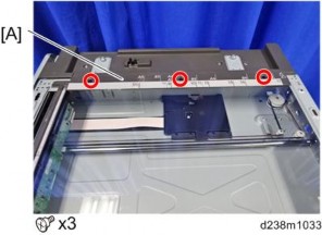
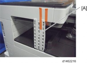
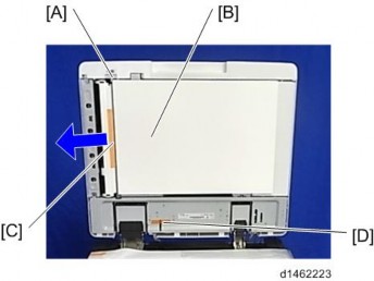
Interface cable [A]
Paper exit tray [A] ![]() ×2)
×2)

Main Unit
Cover [A] ![]() ×2)
×2)

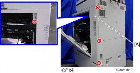
Screw on the finisher [A] ![]() ×1)
×1)
Finisher [A]
Rear cover (page 6)
INTERNAL FINISHER SR3180 (D766)
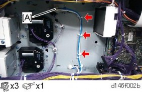
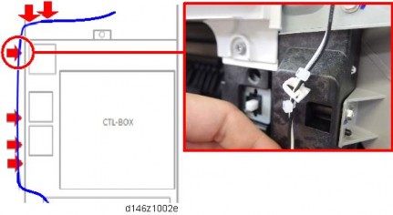
Disconnect the connector and release the clamps ![]() ×1,
×1, ![]() ×2).
×2).
Turn the finisher [A] over.
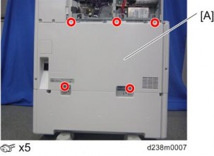
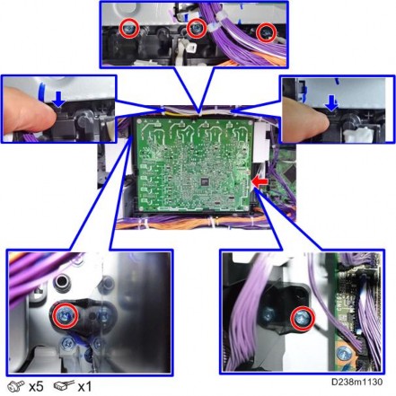
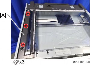
Remove the screws securing the stapler unit [A] ![]() ×5).
×5).
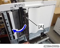
Stapler unit [A] ![]() ×1)
×1)
Bracket [A] from the stapler unit ![]() ×2)
×2)
Paper exit cover (page 7)
INTERNAL FINISHER SR3180 (D766)
Finisher front cover [A] ![]() ×2)
×2)
Finisher front cover (page 5)
Finisher upper cover [A] ![]() ×1)
×1)
Finisher (page 1)
Rear cover ![]() ×2)
×2)
The screw on the right (when you are facing the rear cover [A]) is a step screw
Internal Finisher (page 1)
Paper exit cover [A] ![]() ×2)
×2)
INTERNAL FINISHER SR3180 (D766)
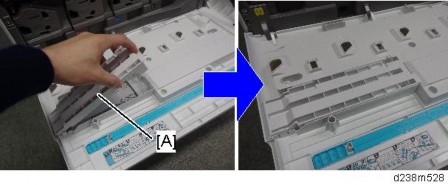
1. Paper exit tray [A] ![]() ×2)
×2)

Rear cover (page 6)
Remove the entrance sensor [A] together with the bracket ![]() ×1,
×1, ![]() ×1).
×1).
Entrance sensor [A] ![]() ×1,
×1, ![]() ×1)
×1)
Finisher upper cover (page 5)
Remove the screw ![]() ×1).
×1).
INTERNAL FINISHER SR3180 (D766)
Remove the side-to-side registration sensor [A] together with the bracket ![]() ×1).
×1).

Side-to-side registration sensor [A]
Rear cover (page 6)
Remove the screw ![]() ×1).
×1).
Open/close door switch [A] ![]() ×1).
×1).
Finisher front cover (page 5)
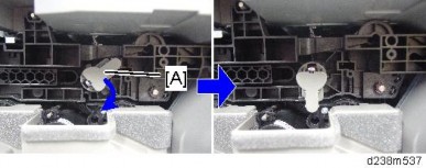
Remove the shift HP sensor [A] together with the bracket ![]() ×1,
×1, ![]() ×1).
×1).

INTERNAL FINISHER SR3180 (D766)
Shift HP sensor [A] ![]() ×1)
×1)

Finisher upper cover (page 5)
Remove the screw ![]() ×1).
×1).
Paper exit sensor [A] ![]() ×1)
×1)
Paper exit cover (page 7)
Remove the screw and release the clamp ![]() ×1,
×1, ![]() ×1).
×1).

INTERNAL FINISHER SR3180 (D766)
Paper exit pressure HP sensor [A] ![]() ×1)
×1)
Remove the screw ![]() ×1).
×1).
Junction gate motor HP sensor [A] ![]() ×1,
×1, ![]() ×1)
×1)
Paper exit cover (page 7)
INTERNAL FINISHER SR3180 (D766)
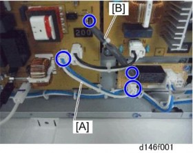
Paper exit full sensor 1 [A], paper exit full sensor 2 [B] ![]() ×1, and
×1, and ![]() ×1, for each sensor)
×1, for each sensor)
Stapler unit (page 3)
Loosen the screw and release the clamp ![]() ×1,
×1, ![]() ×1).
×1).
Remove the stapler drive HP sensor [A] from the bracket ![]() ×1,
×1, ![]() ×1).
×1).
1. Finisher front cover (page 5)
2. Shift motor [A] ![]() ×2,
×2, ![]() ×1,
×1, ![]() ×2)
×2)
Finisher front cover (page 5)
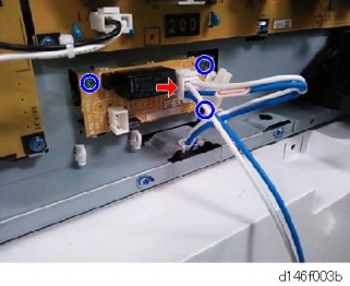
Disconnect the connector attached to the transport motor [A] ![]() ×1).
×1).
INTERNAL FINISHER SR3180 (D766)
Loosen the screw securing the spring bracket [A], and then release the tension on the belt ![]() ×1).
×1).
Transport motor [A] ![]() ×2)
×2)
Paper output cover (page 7)
Release the clamp ![]() ×1).
×1).
Junction gate motor [A] ![]() ×2,
×2, ![]() ×1)
×1)

Paper exit cover (page 7)
Rear cover (page 6)
INTERNAL FINISHER SR3180 (D766)
Release the clamp ![]() ×1).
×1).

Remove the screws on the bracket [A] ![]() ×2).
×2).
Paper exit pressure motor [A] ![]() ×1)
×1)
Stapler unit (page 3)
Stapler drive HP sensor (page 15)
Stapler drive motor [A] ![]() ×2)
×2)