CONTROLLER BOARD 1
SHIFT MOTOR 2
INTERNAL SHIFT TRAY SH3070 (D691) 3
PARTS LAYOUT 3
MECHANISM 4
Upper tray drive mechanism 4
Position detection 4
SM i D691
This manual uses several symbols and abbreviations. The meaning of those symbols and abbreviations are as follows:
Symbol | What it means |
| Clip ring |
| Screw |
| Connector |
| Clamp |
| E-ring |
| Flat Flexible Cable |
| Timing Belt |
SEF | Short Edge Feed [A] |
LEF | Long Edge Feed [B] |
K | Black |
C | Cyan |
M | Magenta |
Y | Yellow |
B/W, BW | Black and White |
FC | Full color |

Adobe, Acrobat, PageMaker, PostScript, and PostScript 3 are either registered trademarks or trademarks of Adobe Systems Incorporated in the United States and/or other countries.
The Bluetooth® word mark and logos are registered trademarks owned by Bluetooth SIG, Inc. and any use of such marks by Ricoh Company, Ltd. is under license.
Firefox and Thunderbird are registered trademarks of the Mozilla Foundation. Google, Android, and Chrome are trademarks of Google Inc.
iOS® is a registered trademark or trademark of Cisco Systems, Inc. and/or its affiliates in the United States and certain other countries.
Java is a registered trademark of Oracle and/or its affiliates.
JAWS® is a registered trademark of Freedom Scientific, Inc., St. Petersburg, Florida and/or other countries.
Kerberos is a trademark of the Massachusetts Institute of Technology (MIT). Linux is a registered trademark of Linus Torvalds.
Macintosh, OS X, Bonjour, Safari, and TrueType are trademarks of Apple Inc., registered in the
U.S. and other countries.
Microsoft, Windows, Windows Server, Windows Vista, Internet Explorer, and Outlook are either registered trademarks or trademarks of Microsoft Corp. in the United States and/or other countries.
PictBridge is a trademark.
QR Code is a registered trademark of DENSO WAVE INCORPORATED in Japan and in other countries.
"Red Hat" is a registered trademark of Red Hat, Inc. The SD and SD logo are trademarks of SD-3C, LLC. UNIX is a registered trademark of The Open Group.
UPnP is a trademark of UPnP Implementers Corporation.

This product includes RSA BSAFE® Cryptographic software of EMC Corporation. RSA and BSAFE are registered trademarks or trademarks of EMC Corporation in the United States and other countries.
The proper names of Internet Explorer 6, 7, and 8 are as follows:
Microsoft® Internet Explorer® 6
Windows® Internet Explorer® 7
Windows® Internet Explorer® 8
The proper names of the Windows operating systems are as follows:
The product names of Windows Vista are as follows: Microsoft® Windows Vista® Ultimate
Microsoft® Windows Vista® Business Microsoft® Windows Vista® Home Premium Microsoft® Windows Vista® Home Basic Microsoft® Windows Vista® Enterprise
The product names of Windows 7 are as follows: Microsoft® Windows® 7 Home Premium Microsoft® Windows® 7 Professional
Microsoft® Windows® 7 Ultimate Microsoft® Windows® 7 Enterprise
The product names of Windows 8 are as follows: Microsoft® Windows® 8
Microsoft® Windows® 8 Pro Microsoft® Windows® 8 Enterprise
The product names of Windows 8.1 are as follows: Microsoft® Windows® 8.1
Microsoft® Windows® 8.1 Pro Microsoft® Windows® 8.1 Enterprise
The product names of Windows 10 are as follows: Microsoft® Windows® 10 Home Premium Microsoft® Windows® 10 Pro
Microsoft® Windows® 10 Enterprise Microsoft® Windows® 10 Education
The product names of Windows Server 2003 are as follows: Microsoft® Windows Server® 2003 Standard Edition Microsoft® Windows Server® 2003 Enterprise Edition
The product names of Windows Server 2003 R2 are as follows: Microsoft® Windows Server® 2003 R2 Standard Edition Microsoft® Windows Server® 2003 R2 Enterprise Edition
The product names of Windows Server 2008 are as follows:
Microsoft® Windows Server® 2008 Standard Microsoft® Windows Server® 2008 Enterprise
The product names of Windows Server 2008 R2 are as follows: Microsoft® Windows Server® 2008 R2 Standard
Microsoft® Windows Server® 2008 R2 Enterprise
The product names of Windows Server 2012 are as follows: Microsoft® Windows Server® 2012 Foundation
Microsoft® Windows Server® 2012 Essentials Microsoft® Windows Server® 2012 Standard
The product names of Windows Server 2012 R2 are as follows: Microsoft® Windows Server® 2012 R2 Foundation
Microsoft® Windows Server® 2012 R2 Essentials Microsoft® Windows Server® 2012 R2 Standard
Other product names used herein are for identification purposes only and might be trademarks of their respective companies. We disclaim any and all rights to those marks.
Microsoft product screen shots reprinted with permission from Microsoft Corporation.
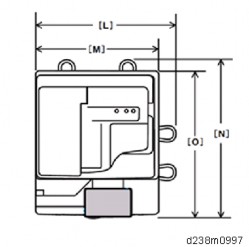
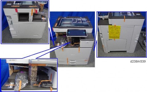
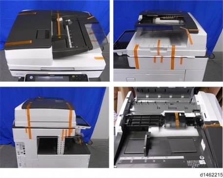
INTERNAL SHIFT TRAY SH3070 (D691)
Shift tray [A]

Upper tray [A]

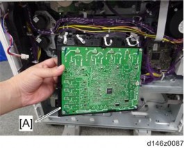
Controller board [A]

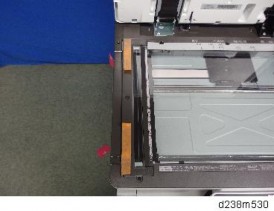
Upper tray (page 1)
Interlocking plate [A]

Rotating plate [A]

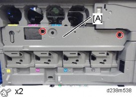
Shift motor [A] ![]() ×1)
×1)

INTERNAL SHIFT TRAY SH3070 (D691)

No. | Description | No. | Description |
1 | Upper tray | 3 | Rotating plate |
2 | Interlocking plate | 4 | Feeler |

No. | Description | No. | Description |
1 | Shift motor | 3 | Controller board |
2 | Position sensor |
Upper tray drive mechanism
The upper tray is moved by the shift motor through a rotor plate and interlocking plate.
Position detection
The position sensor is switched ON (unblocked)/OFF (blocked) by an actuator on the rotating plate.
R EVI SIO N HIS TORY | ||
Page | Date | Added/ Updated/ New |
None | ||
REAR COVER 1
THE AIM OF ANTI-TIP COMPONENTS AND PRECAUTIONS 1
REAR COVER 1
TRAY LIFT MOTOR 2
TRAY LIFT MOTOR 2
TRANSPORT MOTOR 3
TRANSPORT MOTOR 3
PAPER FEED MOTOR 3
PAPER FEED MOTOR 3
CONTROLLER BOARD 4
CONTROLLER BOARD 4
TRANSPORT SENSOR, LIMIT SENSOR, PAPER END SENSOR, PAPER FEED SENSOR 5
TRANSPORT SENSOR, LIMIT SENSOR, PAPER END SENSOR, PAPER FEED SENSOR 5
PAPER FEED UNIT 8
PAPER FEED UNIT 8
PICK-UP ROLLER, FEED ROLLER, FRICTION ROLLER 11
PICK-UP ROLLER, FEED ROLLER, FRICTION ROLLER 11
PAPER FEED UNIT PB3150 (D694) 13
PARTS LAYOUT 13
MECHANISM 15
Paper feed separation mechanism 15
Drive mechanism 15
Separation roller/pick-up roller release mechanism 15
Paper feed transport mechanism 16
Tray bottom plate lift 17
Paper size detection 18
Remaining paper/paper end detection 20
This manual uses several symbols and abbreviations. The meaning of those symbols and abbreviations are as follows:
| Clip ring |
| Screw |
| Connector |
| Clamp |
SEF | Short Edge Feed [A] |
LEF | Long Edge Feed [B] |

Microsoft®, Windows®, and MS-DOS® are registered trademarks of Microsoft Corporation in the United States and /or other countries.
PostScript® is a registered trademark of Adobe Systems, Incorporated.
PCL® is a registered trademark of Hewlett-Packard Company. Ethernet® is a registered trademark of Xerox Corporation.
PowerPC® is a registered trademark of International Business Machines Corporation.
Other product names used herein are for identification purposes only and may be trademarks of their respective companies. We disclaim any and all rights involved with those marks.
PAPER FEED UNIT PB3150 (D694)
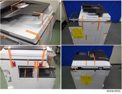
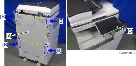
The anti-tip components are necessary for meeting the requirements of IEC60950-1, the international standard for safety.
The aim of these components is to prevent the products, which are heavy in weight, from toppling as a result of people running into or leaning onto the products, which can lead to serious accidents such as persons becoming trapped under the product. (U.S.: UL60950-1, Europe: EN60950-1) Therefore, removal of such components must always be with the consent of the customer.
Do not remove them at your own judgment.
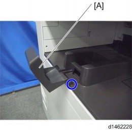
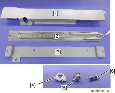
Rear lower gap cover [A] (hook×2)

Securing brackets [A] ![]() ×1 each)
×1 each)

Rear cover [A] ![]() ×4)
×4)

Rear cover (page 1)
Tray lift motor [A] ![]() ×2,
×2, ![]() ×1).
×1).

PAPER FEED UNIT PB3150 (D694)
Rear cover (page 1)
Transport motor [A] ![]() ×2,
×2, ![]() ×1)
×1)

Rear cover (page 1)
Paper feed motor [A] ![]() ×2,
×2, ![]() ×1)
×1)

Rear cover (page 1)
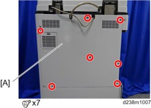
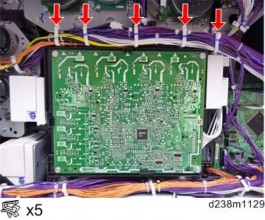
Controller board [A] ![]() ×4,
×4, ![]() ×7)
×7)

PAPER FEED UNIT PB3150 (D694)
Paper feed unit (page 8)
Transport sensor bracket [A] ![]() ×1,
×1, ![]() ×1)
×1)
Transport sensor [A]
Paper feed sensor bracket [A] ![]() ×1,
×1, ![]() ×1)
×1)
Paper feed sensor [A]

Paper end sensor [A] ![]() ×1)
×1)

PAPER FEED UNIT PB3150 (D694)
Limit sensor [A] ![]() ×1)
×1)

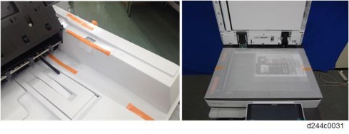
Pull out the paper tray.
Rear cover (page 1)
Right lower cover [A] (hook ×1)
Right rear cover [A] ![]() ×1)
×1)
Open the transport cover [A].
PAPER FEED UNIT PB3150 (D694)
Transport guide [A] (tab ×1)
Harness guide [A] ![]() ×2)
×2)
Release the clamp, and then disconnect the harness at the right rear of the unit ![]() ×1,
×1, ![]() ×1).
×1).
Release the four clamps ![]() ×4).
×4).
Paper feed unit [A] ![]() ×2)
×2)
PAPER FEED UNIT PB3150 (D694)
Paper feed unit (page 8)
Holder [A] ![]() ×1)
×1)
Pick-up roller [A]

Feed roller [A]

Friction roller [A] ![]() ×1)
×1)
PAPER FEED UNIT PB3150 (D694)

No. | Description | No. | Description |
1 | Paper size detection switch | 4 | Feed roller |
2 | Tray set sensor switch | 5 | Transport roller |
3 | Pick-up roller | 6 | Friction roller |


No. | Description | No. | Description |
1 | Paper size detection switch | 8 | Dehumidifying heater |
2 | Controller board | 9 | Paper feed sensor |
3 | Tray set sensor switch | 10 | Paper end sensor |
4 | Tray lift motor | 11 | Vertical transport sensor |
5 | Paper feed motor | 12 | Limit sensor |
6 | Transport motor | 13 | Pick-up solenoid |
7 | Vertical transport cover open/close switch |
PAPER FEED UNIT PB3150 (D694)
Paper feed separation mechanism
The feed system is a RF paper feed system. The paper feed unit has a pick-up roller, feed roller, and friction roller. The feed roller and friction roller are high durability rollers.
Drive mechanism
The pick-up roller and feed roller are driven by the paper feed motor. The transport roller is driven by the transport motor. The friction roller is not driven.

Separation roller/pick-up roller release mechanism
When the right tray is set, the friction roller comes in contact with the feed roller. The pick-up roller touches the top sheet of paper that is to be transported.
When the right tray is opened, contact between the feed roller and friction roller, and contact between the pick-up roller and paper are released.
Paper feed transport mechanism

In order to feed the paper at regular intervals, there is a paper feed sensor between the pick-up roller and the feed roller, and this sensor is used to adjust the paper feed timing.
The paper feed motor turns ON, and feeds the first sheet of paper.
To prevent the next sheet from being transported, the pick-up solenoid turns ON just before the trailing edge of the first sheet passes through the pick-up roller, and the pick-up roller leaves the paper surface.
Just before the trailing edge of the first sheet leaves the paper feed roller, the paper feed motor turns OFF.
However, at this time, if the paper feed sensor does not detect paper (the second sheet is not transported to the paper feed sensor position), the paper feed motor does not turn OFF.
Pre-feed is performed as follows:
The pick-up solenoid turns OFF, and the second sheet of paper is transported to the paper feed sensor position.
When the trailing edge of the second sheet passes the feed roller, the paper feed motor is turned OFF. The pick-up solenoid remains OFF.
Just before the trailing edge of the first sheet passes the feed roller, the pick-up solenoid turns OFF. The pick-up roller is brought into contact with the paper surface.
When the first sheet has been transported a specified distance by the downstream transport roller, the paper feed motor turns ON to feed the second sheet.
PAPER FEED UNIT PB3150 (D694)
Tray bottom plate lift
When the paper feed tray is set in the main frame, the tray set sensor switch turns ON. The coupling of the lift motor connects with the shaft at the rear of the tray, and the motor rotates to lift the tray bottom plate. The tray bottom plate rises until the paper surface lifts up the pick-up roller and the upper limit sensor turns OFF (the sensor is blocked). The tray is now ready to feed.
When the paper feed tray is removed, the coupling is disengaged, and the bottom plate descends. At this time, the lift motor rotates until the coupling returns to the home position.

No. | Description | No. | Description |
1 | Lift motor | 3 | Tray shaft (rear) |
2 | Coupling | 4 | Tray bottom plate |

No. | Description | No. | Description |
1 | Limit sensor | 2 | Pick-up roller |
Paper size detection
The end fence is linked mechanically with the size detection actuator. When the end fence is moved, the size detection actuator also moves.
When the paper feed tray is set, 4 paper size detection switches turn ON/OFF depending on the position of the size detection actuator. Paper size is detected by a combination of these switches.

No. | Description | No. | Description |
1 | End fence | 3 | Size detection actuator |
2 | Size sensor switch | 4 | Tray set sensor switch |
PAPER FEED UNIT PB3150 (D694)
Paper size detection switch operation
Paper size | Size detection switch | |||
SW4 | SW3 | SW2 | SW1 | |
SRA3 (12”×18”) | 1 | 0 | 1 | 0 |
A3 (DLT) | 0 | 1 | 0 | 0 |
B4 (LG) | 0 | 0 | 1 | 1 |
0 | 1 | 1 | 1 | |
A4_SEF | 1 | 1 | 1 | 0 |
LT_SEF | 1 | 1 | 0 | 0 |
B5_SEF | 1 | 0 | 0 | 0 |
A4_LEF (LT_LEF) | 0 | 0 | 0 | 1 |
B5_LEF (Exe_LEF) | 0 | 0 | 1 | 0 |
A5_LEF | 0 | 1 | 0 | 1 |
Remaining paper/paper end detection
Remaining paper detection
Remaining paper in the paper feed tray is detected by a combination of ON/OFF status (contact/non-contact) of contact-type remaining paper sensors (boards) CN-3 and CN-5. When the amount of remaining paper decreases, and the lift motor rotates, the remaining paper sensors CN-3 and CN-5 in the motor are turned ON/OFF.
The following 4 levels of remaining paper can be detected.
Remaining paper | 100% | 70% | 30% | 10% |
CN-3 | OFF | ON | ON | OFF |
CN-5 | OFF | OFF | ON | ON |
Control panel display | 4 bars | 3 bars | 2 bars | 1 bar |
Paper end detection
When there is no more paper in the paper feed tray, the paper end feeler turns ON the paper end sensor (the sensor is unblocked).

No. | Description | No. | Description |
1 | Paper end sensor | 3 | Slot |
2 | End feeler |
R EVI SIO N HIS TORY | ||
Page | Date | Added/ Updated/ New |
None | ||
PUNCH UNIT 1
PUNCH UNIT 1
CONTROLLER BOARD 4
CONTROLLER BOARD 4
PUNCH UNIT HOME POSITION SENSOR 5
PUNCH UNIT HOME POSITION SENSOR 5
PUNCH MOTOR 6
PUNCH MOTOR 6
PUNCH UNIT MOTOR PULSE SENSOR 7
PUNCH UNIT MOTOR PULSE SENSOR 7
HORIZONTAL REGISTRATION TRANSPORT UNIT HOME POSITION SENSOR 8
HORIZONTAL REGISTRATION TRANSPORT UNIT HOME POSITION SENSOR 8
HORIZONTAL REGISTRATION TRANSPORT UNIT MOTOR 9
HORIZONTAL REGISTRATION TRANSPORT UNIT MOTOR 9
PUNCHING UNIT 11
PUNCHING UNIT 11
HORIZONTAL REGISTRATION SENSOR UNIT HOME POSITION SENSOR 13
HORIZONTAL REGISTRATION SENSOR UNIT HOME POSITION SENSOR .. 13 1.10 HORIZONTAL REGISTRATION SENSOR UNIT MOTOR 15
1.10.1 HORIZONTAL REGISTRATION SENSOR UNIT MOTOR 15
PUNCH HOPPER FULL SENSOR 16
HORIZONTAL REGISTRATION SENSOR 17
PUNCH UNIT PU3040 (D716) 18
PARTS LAYOUT 18
MECHANISM 20
Transport mechanism 20
Horizontal registration transport unit mechanism 20
Horizontal registration sensor unit mechanism 21
Punch unit mechanism 22
SM i D716
Punch mechanism 22
Punching position changing mechanism 23
This manual uses several symbols and abbreviations. The meaning of those symbols and abbreviations are as follows:
| Clip ring |
| Screw |
| Connector |
| Clamp |
SEF | Short Edge Feed |
LEF | Long Edge Feed |

Short Edge Feed (SEF)
Long Edge Feed (LEF)
Microsoft®, Windows®, and MS-DOS® are registered trademarks of Microsoft Corporation in the United States and /or other countries.
PostScript® is a registered trademark of Adobe Systems, Incorporated.
PCL® is a registered trademark of Hewlett-Packard Company. Ethernet® is a registered trademark of Xerox Corporation.
PowerPC® is a registered trademark of International Business Machines Corporation.
Other product names used herein are for identification purposes only and may be trademarks of their respective companies. We disclaim any and all rights involved with those marks.
PUNCH UNIT PU3040 (D716)
Open the front cover [A].
Left upper cover [A] ![]() ×1)
×1)

Left rear cover [A] ![]() ×2)
×2)
Interface cable [A]

Internal finisher [A] ![]() ×1)
×1)

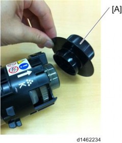
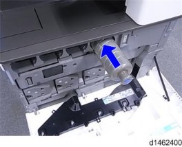
Punch hopper [A]
PUNCH UNIT PU3040 (D716)
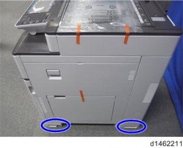
Punch unit front cover [A] ![]() ×1)
×1)
Punch unit [A] ![]() ×1)
×1)
Punch unit (page 1).
Turn over the punch unit.
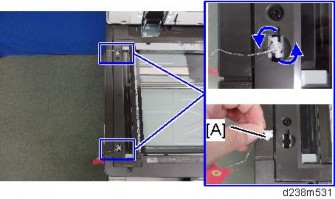
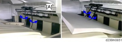
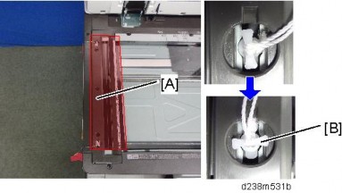
Control plate cover [A]
Release the claws (blue circles). Lift the plate cover in the direction of the blue arrow.
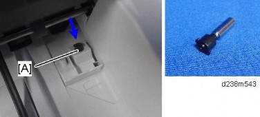
Controller board [A] ![]() ×2,
×2, ![]() ×7)
×7)
PUNCH UNIT PU3040 (D716)
Punch unit (page 1)
Upper rear cover [A] ![]() ×1)
×1)

Push out the punch unit [A].
Punch unit home position sensor [A] ![]() ×1)
×1)
Upper rear cover (page 5)
Punch motor unit [A] ![]() ×2,
×2, ![]() ×2,
×2, ![]() ×3)
×3)

Punch motor [A] ![]() ×2)
×2)
PUNCH UNIT PU3040 (D716)
Upper rear cover (page 5)
Punch unit motor pulse sensor [A] ![]() ×1,
×1, ![]() ×1)
×1)

Punch Unit (page 1)
Horizontal registration transport unit home position sensor unit [A] ![]() ×1,
×1, ![]() ×1)
×1)
Horizontal registration transport unit home position sensor [A]

PUNCH UNIT PU3040 (D716)
Upper rear cover (page 5)
Pull the bracket forward [A] ![]() x2).
x2).
Release the two clamps ![]() x2)
x2)
Bracket with the horizontal registration transport unit motor ![]() x3,
x3, ![]() x2)
x2)
Horizontal registration transport unit motor [A] ![]() x2, timing belt x1)
x2, timing belt x1)
PUNCH UNIT PU3040 (D716)
Punch Unit (page 1 ).
Upper cover [A] ![]() ×2).
×2).

Horizontal registration transport unit motor unit (page 9)
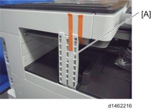
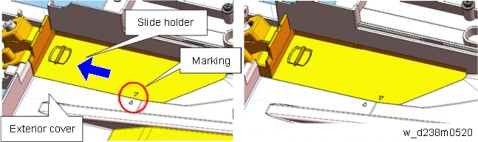
Upper entrance guide plate [A] ![]() ×3)
×3)
To prevent the guide plate from dropping, set the movable parts [A] into the groove as shown by the blue circles.

When attaching the guide plate, shift the movable parts toward the left.
Punching unit [A] ![]() ×1,
×1, ![]() ×3,
×3, ![]() ×7)
×7)
PUNCH UNIT PU3040 (D716)
Upper cover (page 11)
Upper entrance guide plate (page 11)
Spring [A], bracket [B] ![]() ×1)
×1)
Horizontal registration sensor unit [A] ![]() ×6,
×6, ![]() ×1)
×1)

When reinstalling the horizontal registration sensor unit, make sure that the protruded part of the joint [A] fits into the groove on the cam [B].

Horizontal registration sensor unit home position sensor [A] ![]() ×1)
×1)
