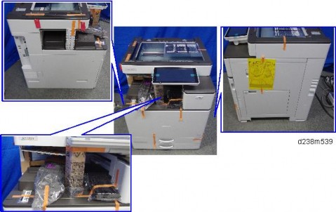
INTERNAL FINISHER SR3130 (D690)
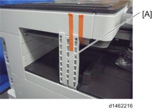
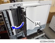
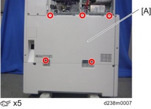
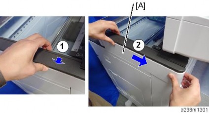
Pull the finisher [A]

Finisher front cover [A] ![]() ×2)
×2)

Finisher front cover (page 3)
Finisher upper cover [A] ![]() ×2)
×2)

Internal finisher (page 1)
Finisher rear cover [A] ![]() ×2)
×2)

INTERNAL FINISHER SR3130 (D690)
1. Left lower cover [A] ![]() ×2)
×2)
Paper exit tray [A] ( ×2).
2.

Paper exit tray (page 5)
Paper exit cover [A] ![]() ×3,
×3, ![]() ×3,
×3, ![]() ×2).
×2).

INTERNAL FINISHER SR3130 (D690)
When a controller board is replaced, use the same DIP switch settings as those of the controller board before replacement.
Finisher front cover (page 3)
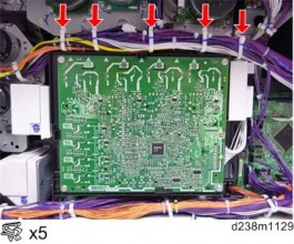
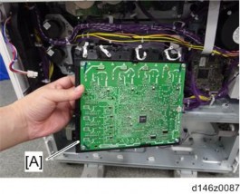
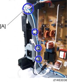
Controller board [A] ![]() ×3,
×3, ![]() ×all, plastic rivet×1)
×all, plastic rivet×1)

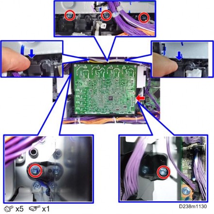
Release four clamps and remove the harness bracket [A] on the controller board bracket. ![]() ×4)
×4)

Controller board bracket [A] ![]() x2)
x2)

INTERNAL FINISHER SR3130 (D690)
Internal finisher (page 1)
Open/Close upper cover [A] ![]() ×2)
×2)

Entrance sensor unit [A] ![]() ×1,
×1, ![]() ×1,
×1, ![]() ×1)
×1)

Entrance sensor [A]

Paper exit tray (page 5)
Paper exit full sensor [A] ![]() ×1,
×1, ![]() ×1)
×1)

INTERNAL FINISHER SR3130 (D690)
Paper exit cover (page 6)
Stack Height Lever HP Sensor [A] ![]() ×1)
×1)

Paper exit cover (page 6)
Paper surface sensor [A] ![]() ×1)
×1)

Finisher upper cover (page 4)
Transport sensor unit [A] ![]() ×1,
×1, ![]() ×1,
×1, ![]() ×1)
×1)

Transport sensor [A]

INTERNAL FINISHER SR3130 (D690)
Finisher upper cover (page 4)
Finisher rear cover (page 4)
Rotate the timing belt [A], and release the positioning roller arm unit [B] from the positioning roller HP sensor [C].

Positioning roller home position sensor unit [A] ![]() ×1,
×1, ![]() ×1,
×1, ![]() ×1)
×1)
Positioning roller home position sensor [A]
Controller board (page 7)
Rotate the paper exit guide plate gear [A] counterclockwise, and release the paper exit guide plate [B] from the paper exit guide plate HP sensor [C].
Paper Exit Guide Plate Home Position Sensor [A] ![]() ×1)
×1)

INTERNAL FINISHER SR3130 (D690)
Controller board bracket (page 7)
Shift roller home position sensor unit [A] ![]() ×1,
×1, ![]() ×1,
×1, ![]() ×2)
×2)
Shift roller home position sensor [A]

Controller board bracket (page 7)
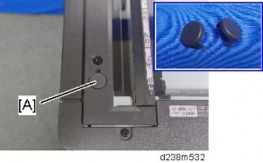
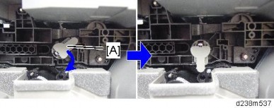
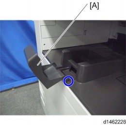
Knob [A]
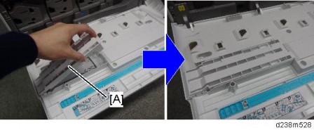
Entrance cover [A] ( ×2)
3.
Stapler home position sensor unit [A] ![]() ×1,
×1, ![]() ×1)
×1)
INTERNAL FINISHER SR3130 (D690)
Stapler home position sensor [A]
If it is difficult to remove or attach the sensor, push the stapler unit inside.
Paper exit cover (page 6)
Jogger fence home position sensor (front) unit [A] ![]() ×1,
×1, ![]() ×1,
×1, ![]() ×1)
×1)
Jogger fence home position sensor (front) [A]
INTERNAL FINISHER SR3130 (D690)
Paper exit cover (page 6)
Jogger fence home position sensor (rear) unit [A] ![]() ×1,
×1, ![]() ×1)
×1)

Jogger fence home position sensor (rear) [A]
Paper exit cover (page 6)
Paper exit roller unit [A] ![]() ×1)
×1)
Stapler tray jam sensor unit [A] ![]() ×1,
×1, ![]() ×1,
×1, ![]() ×1)
×1)
Stapler tray jam sensor [A] ![]() ×1)
×1)
INTERNAL FINISHER SR3130 (D690)
Jogger fence motor (rear) (page 30)
Jogger fence motor (rear) bracket [A] ![]() ×2,
×2, ![]() ×3)
×3)
Paper sensor unit [A] ![]() ×1,
×1, ![]() ×1,
×1,![]() ×1)
×1)
Paper sensor [A]
When installing this sensor, be careful not to damage the sensor actuator.
Finisher rear cover (page 4)
Finisher right rear bracket [A] ![]() ×2)
×2)
Entrance motor [A] ![]() ×2,
×2, ![]() ×1, Timing belt×1)
×1, Timing belt×1)

INTERNAL FINISHER SR3130 (D690)
Paper exit tray (page 5)
Tray lift motor unit [A] ![]() ×2,
×2, ![]() ×1,
×1, ![]() ×1)
×1)
Cam [A], bearing [B] ![]() ×1)
×1)
Tray lift motor [A] ![]() ×2)
×2)
Paper exit cover (page 6)
Stack height lever motor [A] ![]() ×2,
×2, ![]() ×1)
×1)
Controller board (page 7)
Paper exit guide plate motor [A] ![]() ×2,
×2, ![]() ×1,
×1, ![]() ×1)
×1)
INTERNAL FINISHER SR3130 (D690)
Paper exit cover (page 6)
Finisher rear cover (page 4)
Rear rail [A] ![]() ×2)
×2)

Positioning roller motor [A] ![]() ×2,
×2, ![]() ×1)
×1)

After attaching, rotate the knob, and check that all gear trains can rotate.
After attachment, when the cam [A] is rotated, check that the link [B] interlocks.
Controller board bracket (page 7)
Pulley [A], Timing belt [B] ![]() ×1)
×1)
Shift motor unit [A] ![]() ×2,
×2, ![]() ×1,
×1, ![]() ×1)
×1)

INTERNAL FINISHER SR3130 (D690)
Shift motor [A] ![]() ×2).
×2).
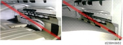
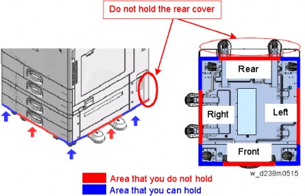
When placing the finisher upside down, be careful not to deform the frame.
Paper exit cover (page 6)
Release the four clamps ![]() ×4).
×4).
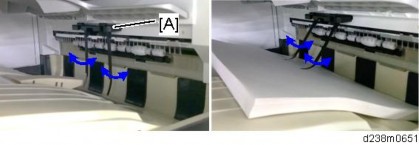
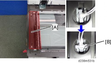
Place the internal finisher upside down on the table while holding the parts shown below [A].

Hold the parts [A] shown below to lift the internal finisher. Otherwise, other brackets and parts may be deformed.
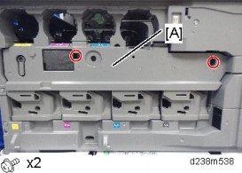
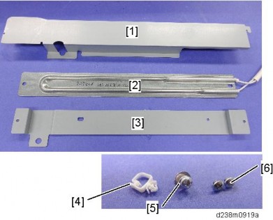
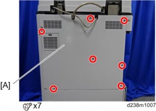
Base cover [A] ![]() ×3)
×3)

INTERNAL FINISHER SR3130 (D690)
Stapler retreat motor ![]() ×2,
×2, ![]() ×1)
×1)
Base cover (page 28)
Jogger fence motor (front) [A] ![]() ×2,
×2, ![]() ×1, Timing belt×1)
×1, Timing belt×1)
During re-assembly, remove the jogger fence motor (rear) bracket, and check that the motor pulley has not separated from the timing belt.
Jogger fence motor (rear) [A] ![]() ×2,
×2, ![]() ×1, Timing belt×1)
×1, Timing belt×1)
During re-assembly, check that the motor pulley has not separated from the timing belt.
INTERNAL FINISHER SR3130 (D690)
Paper exit cover (page 6)
Controller board (page 7)
Finisher rear cover (page 4)
Pulley [A], Timing belt [B] ![]() ×1).
×1).
Transport Motor [A] ![]() ×2,
×2, ![]() ×1, Timing belt×1)
×1, Timing belt×1)
Transport motor (page 31)
Controller board bracket (page 7) 3. Gear [A] ![]() ×1)
×1)
Two clip rings [A] and Shaft bracket [B] ![]() ×2).
×2).
Remove the screws of the fan [A] and then lay it down ![]() ×2).
×2).
INTERNAL FINISHER SR3130 (D690)
Paper Exit Motor [A] ![]() ×2,
×2, ![]() ×1).
×1).

Controller board bracket (page 7)
Insert the stapler unit [A] into the rear.

Rear trailing edge fence [A] ![]() ×2)
×2)

Stapler home position sensor (page 16)
Cover open/close switch unit [A] ![]() ×1,
×1, ![]() ×2)
×2)
INTERNAL FINISHER SR3130 (D690)
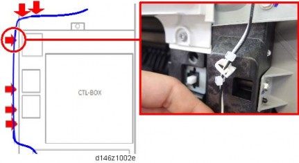
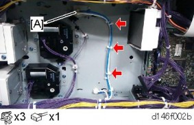
Harness guide unit [A] ![]() ×1)
×1)
Move the stapler unit to the front, and remove the cartridge [A].

During re-assembly, install the cartridge last.
Remove the unit fixing screw of the stapler unit. ![]() ×1)
×1)
Stapler unit [A] ![]() ×2,
×2, ![]() ×2)
×2)

INTERNAL FINISHER SR3130 (D690)

No. | Description | No. | Description |
1 | Paper exit tray | 7 | Transport roller |
2 | Paper ejection roller | 8 | Entrance roller |
3 | Paper exit open/close guide plate | 9 | Stapler |
4 | Positioning roller | 10 | Staple tray (jogger) |
5 | Shift roller | 11 | Stack height detection lever |
6 | Reverse roller | 12 | Full sensor |

No. | Description | No. | Description |
1 | Paper exit open/close guide plate | 8 | Transport roller |
2 | Paper exit open/close guide plate motor | 9 | Reverse roller |
3 | Positioning roller motor | 10 | Shift roller |
4 | Positioning roller unit | 11 | Positioning roller |
5 | Transport motor | 12 | Paper ejection roller |
6 | Entrance motor | 13 | Paper exit motor |
7 | Entrance roller |
INTERNAL FINISHER SR3130 (D690)

No. | Description | No. | Description |
1 | Paper exit tray | 6 | Stapler |
2 | Stack height detection lever | 7 | Jogger motor |
3 | Staple tray (jogger) | 8 | Stapler retreat motor |
4 | Shift motor | 9 | Stack height lever motor |
5 | Shift roller | 10 | Tray lift motor |

No. | Description | No. | Description |
1 | Entrance motor | 4 | Transport motor |
2 | Transport sensor | 5 | Paper exit motor |
3 | Entrance sensor |
INTERNAL FINISHER SR3130 (D690)

No. | Description | No. | Description |
1 | Positioning roller motor | 4 | Shift roller Home Position sensor |
2 | Positioning roller Home Position sensor | 5 | Paper exit guide plate motor |
3 | Paper exit guide plate Home Position sensor |

No. | Description | No. | Description |
1 | Stapler retreat motor | 6 | Jogger fence motor (front) |
2 | Jogger fence Home Position sensor (rear) | 7 | Jogger fence Home Position sensor (front) |
3 | Jogger fence motor (rear) | 8 | Stapler Home Position sensor |
4 | Paper sensor | 9 | Stapler motor |
5 | Stapler tray jam sensor |
INTERNAL FINISHER SR3130 (D690)

No. | Description | No. | Description |
1 | Stack height lever HP sensor | 5 | Controller board |
2 | Paper surface sensor | 6 | Full sensor |
3 | Stack height lever motor | 7 | Tray lift motor |
4 | Cover open/close switch |
Straight paper ejection mechanism
Paper ejected from the printer unit is transported by a transport roller and eject roller via an entrance roller. These are driven by entrance motor, transport motor and eject motor which permit linear speed correspondence. The paper exit driven roller stands by at a certain distance from the paper exit roller, and its descent/ascent is performed by an eject guide plate movable motor depending on the detection timing of the sensors (motor operates CW/CCW).
The paper eject open/close guide plate descent/ascent timings are as follows:
Descent: Paper rear edge passes entrance sensor
Ascent: Paper rear edge passes transport sensor
The eject guide plate is provided with a Home Position sensor which detects the home position during ascent.

No. | Description | No. | Description |
1 | Paper exit motor | 8 | Transport sensor |
2 | Paper exit roller | 9 | Transport motor |
3 | Paper exit open/close guide plate | 10 | Transport roller |
4 | Paper exit guide plate motor | 11 | Entrance sensor |
5 | Paper exit open/close guide plate Home Position sensor | 12 | Entrance motor |
6 | Paper exit driven roller | 13 | Entrance roller |
7 | Shift roller |
Shift eject mechanism
INTERNAL FINISHER SR3130 (D690)
As with straight eject, shift eject is also done by transporting the paper to a transport roller and an eject roller via an entrance roller.
In shift operation, a shift roller is moved from front to back during transport by the driver of a shift motor.
Shift roller operation timings are as follows:
Shift operation: Paper rear edge passes entrance sensor
Return to original position: Paper rear edge passes transport sensor The shift roller detects the home position by a Home Position sensor.
The shift roller motor operates CW/CCW, and shifts the paper from front to back. The home position is located at the back of the displacement range, and is detected by a Home Position sensor.

No. | Description | No. | Description |
1 | Shift roller | 3 | Shift motor |
2 | Shift roller Home Position sensor |
Staple eject mechanism
Staple eject requires that transported paper is temporarily stored in a staple tray. After rear edge detection of the transported paper is performed by a transport sensor, a positioning roller unit descends and transports it to a staple tray.


Positioning roller ascent/descent mechanism
The positioning roller unit is made to ascend/descend by a positioning roller up/down drive motor (the motor operates CW/CCW), and its position is detected by a Home Position sensor. The positioning roller rotates in the opposite direction to the transport roller, and has the function of transporting paper to the back of the staple tray.
INTERNAL FINISHER SR3130 (D690)
Paper rear edge alignment mechanism
The rear edge of paper transported by the positioning roller is made to project against a rear trailing edge fence by a reverse roller. It rotates continuously until the bundle of paper is ejected after it is stapled.
The reverse roller is driven from a transport roller via a gear, and is always situated above the stapler tray. A driven roller is installed on the side of the stapler tray which reduces wear of the reverse roller.
Paper detection on stapler tray
The stapler tray is provided with the following sensors which detect paper status in the tray.
Paper jam in tray: tray jam sensor
Paper present/absent in tray: paper sensor
Jogger mechanism (paper alignment)
Paper transported to the stapler tray is aligned one sheet at a time by a jogger fence. The jogger fences are driven forwards and backwards independently, and align the paper with the tray center. Jogger fence drives are installed at the front and back. Home Position sensors are also installed at the front and back.
When the paper alignment is performed, the jogger fences move from the home position, and stand by 7 mm away from the paper to be stapled. When the paper is then transported to the tray, the jogger fence (rear) moves according to the paper size and aligns the paper. The jogger fence (rear) stands by 7 mm away from the paper, and again moves 7 mm towards the paper in order to perform paper alignment, so it moves a total of 14 mm. During the paper alignment, the jogger fence (rear) repeats this movement.
[A]: 7mm
[B]: 14mm
No. | Description | No. | Description |
1 | Jogger fence (rear) | 5 | Jogger fence displacement motor (front) |
2 | Jogger fence Home Position sensor (rear) | 6 | Jogger fence Home Position sensor (front) |
3 | Stapler tray | 7 | Jogger fence (front) |
4 | Jogger fence displacement motor (rear) |
Stapler movement mechanism
INTERNAL FINISHER SR3130 (D690)
Stapler specification is as follows:
There are three stapling positions, i.e., one front parallel, one back parallel and two parallel.
30 large sheets or 50 small sheets can be stapled.
To change the stapling position, a mechanism is provided which moves the stapler. The stapler is moved by a stapler motor, and the home position is detected by a Home Position sensor.

No. | Description | No. | Description |
1 | Stapler Home Position sensor | 3 | Stapler retreat motor |
2 | Stapler |
The stapler moves from the home position to the paper size to be stapled, and temporarily stands by. Next, the paper is transported, and after the jogger operation (paper alignment), stapling is performed.
The following picture shows the stapler standby position according to various stapling positions. From the left, there is front parallel one position, back parallel one position, and parallel two positions.
For parallel two positions, the first staple is inserted from the front, and it then moves to the back to perform stapling.
Stapling is performed back and forth, i.e., the second staple is back > front, the third staple is front > back, etc.
[A]: Front parallel, one position [B]: Back parallel, one position [C]: Parallel, two position
Paper eject (bundle eject)
After stapling, the eject paper open/close guide plate descends, and ejects the bundle of paper while gripping it with the eject roller.
Paper press mechanism
For ejected paper, a paper press unit is provided to immobilize the paper above the tray. It is driven by a paper press drive motor (motor operates CW/CCW)
The paper press unit is provided with a paper surface sensor which detects the upper part of the paper, and a Home Position sensor which detects the home position of the paper press unit. The paper surface sensor detects the number of sheets in the tray, and if the number is large, it descends the tray to a suitable position.
Tray drive mechanism
The eject tray has a mechanism which descends the tray to a suitable position. This is driven by a tray drive motor (motor operates CW/CCW). It operates when the paper surface sensor cannot detect paper in the tray, and descends the eject tray until detection is performed.
Tray full detection mechanism
When the eject tray descends to its maximum, a full detect sensor below is covered by the eject tray filler, and it is detected that the top of the tray is full. During full tray detection, paper transport is temporarily stopped. After the paper bundle is released, the tray is raised to a suitable position, and the eject operation is repeated.
INTERNAL FINISHER SR3130 (D690)
No. | Description | No. | Description |
1 | Paper exit tray | 5 | Stack height lever HP sensor |
2 | Stack height detection lever | 6 | Full sensor |
3 | Stack height lever motor | 7 | Tray lift motor |
4 | Paper surface sensor |
REVISION H IST ORY | ||
Page | Date | Added/ Updated/ New |
None | ||