
FINISHER SR3210/ BOOKLET FINISHER SR3220 (D3B8/D3B9)
SP6-160-004 (Replacement Mode for Service)
It is easier to access the following parts for replacement after running SP-6-160-004.
Positioning Roller [A]
The paper exit guide plate moves upwards and the positioning roller pops up in front for easier access.
Reverse Roller [B]
The paper exit guide plate moves upwards and the reverse roller can be accessed.

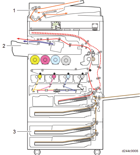
No. | Description | No. | Description |
1 | Booklet tray | 7 | Proof tray |
2 | Paper surface detecting arm | 8 | Junction gate |
3 | Stapler tray | 9 | Relay Guide Plate |
4 | Shift tray | 10 | Stapler unit |
5 | Paper exit guide plate | 11 | Booklet unit |
6 | Paper exit guide |
FINISHER SR3210/ BOOKLET FINISHER SR3220 (D3B8/D3B9)
Drive layout

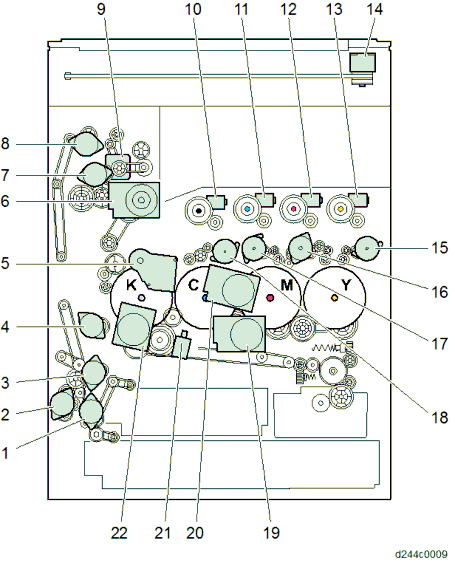
No. | Description | No. | Description |
1 | Edge stopper motor | 12 | Paper exit transport motor |
2 | Folding blade motor | 13 | Feedout Pawl motor |
3 | Folding transport motor | 14 | Stapler unit displacement motor |
No. | Description | No. | Description |
4 | Booklet transport (lower) pressure release motor | 15 | Tray lift motor |
5 | Booklet bundle transport (upper) motor | 16 | Paper exit guide drive motor* |
6 | Shift motor | 17 | Paper guide drive motor* |
7 | Entrance transport motor | 18 | Stapleless stapler transfer motor* |
8 | Junction gate solenoid | 19 | Stapler transfer motor |
9 | Proof transport motor | ||
10 | Paper exit guide plate open/close motor | ||
11 | Positioning roller motor |
* Finisher SR3210 only
Electrical component layout
FINISHER SR3210/ BOOKLET FINISHER SR3220 (D3B8/D3B9)
Transport system

No. | Description | No. | Description |
1 | Intermediate transport (right) paper surface sensor | 9 | Upper cover open/close sensor |
2 | Intermediate transport (left) paper surface sensor | 10 | Proof tray full sensor |
3 | Controller | 11 | Proof paper exit sensor |
4 | Shift HP sensor | 12 | Entrance paper surface sensor |
5 | Shift motor | 13 | Straight transport LED |
6 | Junction gate solenoid | 14 | Entrance jam detection LED |
7 | Proof transport motor | 15 | Stapler jam detection LED |
8 | Entrance transport motor |
Shift system

No. | Description | No. | Description |
1 | Tray lower limit sensor (upper) | 8 | Paper exit guide HP sensor |
2 | Tray lower limit sensor (lower) | 9 | Paper exit guide drive motor |
3 | Shift tray upper limit switch | 10 | Paper exit guide plate open/close motor |
4 | Shift tray paper surface sensor | 11 | Paper exit guide plate HP sensor |
5 | Paper Exit Transport Motor | 12 | Front door switch |
6 | Positioning roller HP sensor | 13 | Tray lift motor |
7 | Positioning roller motor |
FINISHER SR3210/ BOOKLET FINISHER SR3220 (D3B8/D3B9)
Jogger system

No. | Description | No. | Description |
1 | Jogger motor | 5 | Booklet stitch transport (upper) motor |
2 | Paper exit sensor | 6 | Stapler tray paper surface sensor |
3 | Booklet transport (upper) pressure release motor | 7 | Feedout Pawl HP sensor |
4 | Jogger HP sensor | 8 | Feedout Pawl motor |
Stapler/Intermediate transport system

No. | Description | No. | Description |
1 | Stapler transfer motor | 6 | Booklet transport jam detection LED |
2 | Paper Bundle Transport Lower Pressure Release HP Sensor | 7 | Booklet unit jam detection LED1 |
3 | Booklet transport (lower) pressure release motor | 8 | Stopper jam detection LED |
4 | Stapler unit | 9 | Booklet unit jam detection LED2 |
5 | Stapler HP sensor |
FINISHER SR3210/ BOOKLET FINISHER SR3220 (D3B8/D3B9)
Stapleless stapler unit (Finisher SR3210 only)

No. | Description | No. | Description |
1 | Paper guide drive motor | 6 | Stapler transfer motor |
2 | Paper guide HP sensor | 7 | Stapler HP sensor |
3 | Stapleless stapler transfer motor | 8 | Stapleless Stapler drive motor |
4 | Stapleless stapler HP sensor | ||
5 | Stapler transfer motor |
Paper folding system

No. | Description | No. | Description |
1 | Booklet tray full sensor 1 | 6 | Folding cam HP sensor |
2 | Booklet tray full sensor 2 | 7 | Folding blade HP sensor |
3 | Edge stopper motor | 8 | Center-folding paper exit sensor |
4 | Folding blade motor | 9 | Edge stopper paper surface sensor |
5 | Folding transport motor | 10 | Edge stopper HP sensor |
FINISHER SR3210/ BOOKLET FINISHER SR3220 (D3B8/D3B9)
Punch system

No. | Description | No. | Description |
1 | Hopper full sensor | 6 | Horizontal registration unit HP sensor |
2 | Punch unit drive motor | 7 | Horizontal registration correction unit HP sensor |
3 | Punch unit HP sensor | 8 | Horizontal registration correction motor |
4 | Controller | 9 | Horizontal registration correction sensor |
5 | Horizontal registration unit transfer motor |
Separation mechanism
In the separation unit, the transport path of the paper is changed with the junction gate [A] by the junction gate solenoid [B].
The change-over action of the junction gate is as follows.
Mode | Proof mode | Shift mode |
Paper transport path |
|
|
Junction gate solenoid | ON | OFF |
Proof tray transport
The proof paper exit roller, proof transport roller and the intermediate transport roller are driven by the proof transport motor. The entrance transport roller is driven by the entrance transport motor.
Proof tray full detection
FINISHER SR3210/ BOOKLET FINISHER SR3220 (D3B8/D3B9)
The proof tray full sensor [A] is above the proof tray. When a fixed amount of paper is ejected, it switches OFF (blocked), and "Full" is detected.

Shift tray ascent/descent mechanism

Ascent/descent is performed according to the number of sheets of paper (paper surface height) released to the shift tray. This height is detected by the shift tray paper surface sensor [B] switching OFF/ON due to the rear end press lever [A], and is adjusted up and down by the tray lift motor [C] so that the shift tray paper surface sensor switches OFF (blocked).
Ascent
The shift tray paper surface sensor detects the movement upper limit of the shift tray, and disconnects the control circuit of the tray lift motor.
When paper is removed from the shift tray and the shift tray paper surface sensor switches ON (unblocked), the shift tray ascends, and when the sensor switches OFF (blocked), it stops.
Descent
In shift mode
When every 5 sheets of paper are delivered to the shift tray, the tray moves up and down. The shift tray first descends until the shift tray paper surface sensor switches ON (unblocked), and the shift tray then ascends until the sensor switches OFF (blocked).
In stapling mode
When exiting the paper to the shift tray, the tray lift motor switches ON/OFF for a definite time, and the tray height is adjusted.
Shift tray full detection
Small size (Smaller than A4 SEF, LT LEF)
When the shift tray descends and the actuator [A] under the shift tray switches the lower limit sensor (lower) [B] OFF (blocked), shift tray "Full" is detected.
Large size (Larger than B4, LG)
When the shift tray descends and the actuator [A] under the shift tray switches the lower limit sensor (upper) [C] OFF (blocked), shift tray "Full" is detected.

Shift mechanism
The paper is shifted from side to side by the shift roller in the transport path.
FINISHER SR3210/ BOOKLET FINISHER SR3220 (D3B8/D3B9)
The paper exit guide plate floats up from the paper exit roller, and waits for the paper. After the shift paper exit sensor [A] switches ON, the paper exit guide plate is closed, and after the paper is ejected to the tray, the shift roller returns to the home position (center).
This operation is performed for every sheet, and when the shift direction changes (this happens when a new set of prints is fed out), the shift roller shifts in the opposite direction.
The shift roller [C] is moved to left and right by the shift motor [B].
The shift roller HP sensor [D] detects the home position of the shift roller.

Booklet tray
The paper surface detecting arm [A] detects the top of the pile of stapled booklets ejected to the booklet tray.
The arm press [B] presses the bulge of the edges of the booklets from the top. The booklet tray full sensor 1[C] and the booklet tray full sensor 2 [D] detect booklet tray "Full".

Tray full detection changes with the size of paper that has been stapled, and the number of sheets in one bundle. If the tray is full, the machine stops.
Tray status detection
Tray status | Booklet tray full sensor 1 | Booklet tray full sensor 2 |
Standby position | ON | OFF |
Full 1 | ON | ON |
Full 2 | OFF | ON |
Full 3 | OFF | OFF |
Stapled paper eject mechanism
FINISHER SR3210/ BOOKLET FINISHER SR3220 (D3B8/D3B9)
Paper must first be stored in the stapler tray [A]. After the stapler tray paper surface sensor detects the paper sheet rear edge, the approach roller [C] descends, and transports the paper to the stapler tray.
No. | Description | No. | Description |
[A] | Stapler tray | [C] | Approach roller |
[B] | Jogger fence |
Stacking mechanism (approach roller operation)
The rear edges of the paper stacked in the stapler tray are aligned one sheet at a time.
The paper is transferred to the reverse roller [B] by the approach roller [A], driven by the positioning roller motor, after the intermediate transport (left) paper surface sensor turns OFF. The paper is then continuously pressed against the trailing edge fence by the reverse roller [B].

Trailing edge fence operation
The trailing edge fence used depends on the binding mode of the stapler. There are two trailing edge fences, upper and lower.
Upper trailing edge fence
Operated by the booklet transport (upper) pressure release motor.

Binding modes: Edge binding mode (one position)/edge binding mode (two positions), and booklet stitch mode (small sizes: B5, A4, LT)
Lower trailing edge fence
When the stapler moves to the center, the trailing edge fence is depressed by hitting the stapler.
FINISHER SR3210/ BOOKLET FINISHER SR3220 (D3B8/D3B9)
Binding modes: booklet stitch mode (large sizes: LG, B4, A3, DLT, 12"×17.7")

Jogger operation
After the paper rear edges have been aligned by stacking, jogger operation is then performed to align the width.
The jogger fences [B] are opened and closed by the jogger motor [A]. At the start of jogging, the jogger fences [B] stand by in a state where they are opened wider than the paper width. When the rear edge of the transported paper is pressed against the trailing edge fence by the reverse roller, the jogger fences move close to the edges of the paper.
Next, the jogger fences move to the edges, to align the paper.
After jogging is complete, the jogger fences again open, and stand by to receive the next sheet.
The home position of the jogger fences is detected by the jogger HP sensor [C].

Paper exit guide plate open/close mechanism
When paper is stacked in the stapler tray, the paper exit guide plate [A] is opened to cancel the load on the paper exit roller.
When paper is stacked in the stapler tray, the paper exit guide plate remains open from the first page to the last page, and after the stapling operation is finished, the paper exit guide plate is closed, and the paper is ejected by the paper exit roller and release belt.
The switching action of the paper exit guide plate is driven by the paper exit guide plate open/close motor [B] via a link.
The home position of the paper exit guide plate is detected by the paper exit guide plate open/close HP sensor [C].

FINISHER SR3210/ BOOKLET FINISHER SR3220 (D3B8/D3B9)
Stapler displacement mechanism
The stapler unit [A] staples the stack of sheets.
The stapling position changes with the stapling mode and paper size.
When the operation starts after power is switched on, or the front door opens and closes, the main controller board drives the stapler transfer motor [B] to return the stapler unit to the home position.
The stapler unit starts to transfer the paper to the front side of the stapler frame, and when the stapler HP sensor [C] under the stapler unit detects the screen, it temporarily stops. Then, the stapler transfer motor is driven for a predetermined number of pulses. The stapler unit moves to the rear side, and stands by.

To prevent the stapler unit colliding with the feedout pawl and trailing edge fences, a stapler retreat sensor is provided.
Edge binding mode (one position):

Edge binding mode (two positions):

Booklet stitch mode (small sizes: B5, A4, LT):

Booklet stitch mode (large sizes: LG, B4, A3, DLT, 12"×17.7"):

Release mechanism
Paper exits to the shift tray by the feedout pawl and the paper exit roller after the stapling is done.
When the feedout pawl motor [A] turns ON, the release belt is driven and the paper is moved upwards by the feedout pawl [D].
FINISHER SR3210/ BOOKLET FINISHER SR3220 (D3B8/D3B9)
When the stapled stack touches the paper exit roller, the paper exit guide plate [B] closes and the paper is released. To prevent the stack from moving up too much, the feedout pawl motor is stopped temporarily.
The home position of the release belt is detected by the feedout pawl HP sensor [C].

Booklet stitching mechanism
Paper which has been stitched in the center is pressed in by the booklet stitch folding roller with the folding blade.
The paper folded by the folding roller is released by the paper exit shutter, and is stacked in the booklet tray one sheet at a time.
A compact layout is achieved by sharing the edge binding stapler, booklet tray, transport, and stack.
The stapler unit and the folding process unit are divided.
Booklet stitch bundle transport and pressure release
In the case of booklet stitching, the paper must be transported to the stapling position. Booklet transport rollers are provided at two positions, upper and lower. The transport and timing of the rollers which transport the bundle differ according to the paper size.
A3, DLT, 12"×17.7"
After booklet stitching is complete, the (upper) booklet transport pressure release motor operates, and at the same time, the (lower) booklet transport roller starts applying pressure. B4 or smaller
The (lower) booklet transport roller starts to pressurize after a certain amount of paper (as much as the leading edge goes through the nip of the (lower) booklet transport roller) for each size is transferred after booklet stitching is done.
The booklet transport rollers transport the paper and apply pressure.
They transport the paper to the stapling position, and thence to the folding unit. Transport and pressure/release are driven by upper and lower motors.
Upper: Booklet transport (upper) pressure release motor [A] (also performs trailing edge fence retreat)
FINISHER SR3210/ BOOKLET FINISHER SR3220 (D3B8/D3B9)
Lower: Booklet transport (lower) pressure release motor [B]
Edge stopper operation
The paper is transported to the leading edge stopper of the paper folding unit.
The leading edge stopper moves to the standby position according to the folding size.
Folding blade operation
The binding position is pressed by the movement of the folding blade, and pushed in until the folding roller grips.
The movement is performed by front and rear folding cams, and the folding blade moves horizontally.
The rotation of the folding cam is controlled by the folding cam HP sensor, and the folding blade is controlled by the folding blade HP sensor.
This is driven by the folding blade motor.
Folding roller operation
The folding rollers apply pressure up and down by springs, and press the binding parts. When the stitching position reciprocates back and forth, the paper is folded again, and the paper is then ejected.
FINISHER SR3210/ BOOKLET FINISHER SR3220 (D3B8/D3B9)
To prevent fire spreading from the circuit board, a cover [A] is placed over the controller board.


No. | Description | No. | Description |
1 | Hopper full sensor | 6 | Punch unit HP sensor |
2 | Punch drive motor | 7 | Horizontal registration correction unit HP sensor |
3 | Punch HP sensor | 8 | Horizontal registration correction motor |
4 | Controller | 9 | Horizontal registration correction sensor |
5 | Punch unit movement motor |
The punch unit is in the finisher paper feed unit, and when paper transported from the main machine stops, it makes two punch holes in the rear edge of the paper one sheet at a time. Offset in the angle of the paper is corrected by skew correction, and offset in the lateral direction is corrected by moving the punch unit.
Skew Correction
Paper is output from the main machine.
The entrance sensor [A] detects the paper.
The paper is brought into contact with the entrance roller [B].
FINISHER SR3210/ BOOKLET FINISHER SR3220 (D3B8/D3B9)
Skew correction is applied to the paper, and it is transported.

Registration
The horizontal registration correction sensor [A] detects the lateral offset of the paper.
The punch unit moves by the lateral offset detection amount, and completes punching.
Punch hole alignment adjustment
SP | Description |
SP6-100-001 | Sub-scanPunchPosAdj:2K/3K FIN JPN/EU: 2-Hole |
SP6-100-002 | Sub-scanPunchPosAdj:2K/3K FIN NA: 3-Hole |
SP6-100-003 | Sub-scanPunchPosAdj:2K/3K FIN Europe: 4-Hole |
SP6-100-004 | Sub-scanPunchPosAdj:2K/3K FIN NEU: 4-Hole |
SP6-100-005 | Sub-scanPunchPosAdj:2K/3K FIN NA: 2-Hole |
SP6-101-001 | Main-scanPunchPosAdj:2K/3K FIN JPN/EU: 2-Hole |
SP6-101-002 | Main-scanPunchPosAdj:2K/3K FIN NA: 3-Hole |
SP6-101-003 | Main-scanPunchPosAdj:2K/3K FIN Europe: 4-Hole |
SP6-101-004 | Main-scanPunchPosAdj:2K/3K FIN NEU: 4-Hole |
SP6-101-005 | Main-scanPunchPosAdj:2K/3K FIN NA: 2-Hole |

Paper position detection
When the horizontal registration correction sensor [A] of the punch unit detects the leading edge of the paper from the MFP, the horizontal registration correction motor [B] is driven, and starts to move the punch unit to the front.
FINISHER SR3210/ BOOKLET FINISHER SR3220 (D3B8/D3B9)
After the horizontal registration correction sensor detects the paper rear edge (as viewed from the front of the machine), the machine compares it with the paper size set in the MFP. The horizontal registration correction motor is then driven to a predetermined position at the front, and stops the punch unit.
Punch unit movement
The punch unit moves towards the front or the rear according to the paper size. The front-rear movement is driven by the punch unit movement motor [A]. The home position of the punch unit is detected by the punch unit HP sensor [B].
Punch drive
Punching is driven by the punch drive motor [A]. The punch home position is detected by the punch HP sensor [B].
Punch drive motor rotation control feeds back the encoder wheel rotation speed detected by the punch pulse wave count sensor [C] to the punch drive motor.
Punching is performed by moving the punch unit once back and forth, by rotating the punch shaft 180 degrees from the home position.
In the home position, the punch HP sensor is ON. The first sheet is punched by rotating the punch shaft 180 degrees in the forward direction, and is completed when the punch HP sensor switches from OFF to ON. The 2nd sheet is punched by rotating the punch shaft 180 degrees in the reverse direction, and is completed when the punch HP sensor switches from OFF to ON.
For 2 hole punch [D] and 3 hole punch [E], the timings are different.

Punch scrap collection/full detection
FINISHER SR3210/ BOOKLET FINISHER SR3220 (D3B8/D3B9)
Punch scraps are collected by the hopper [A] provided under the punch unit. There is a hopper full sensor [B] in the hopper unit, and when punch scraps fill up to the sensor, the hopper is detected to be full.

RE V IS ION H IST ORY | ||
Page | Date | Added/ Updated/ New |
None | ||
1.1 FAX OPTION TYPE M19 (D3BV-01, -02, -03) 1
ACCESSORY CHECK 1
INSTALLATION PROCEDURE 2
Fax Stamp Installation 6
ADDING FAX APPLICATION ICONS TO THE HOME SCREEN 7
Registering the Function key 7
Function Priority Setting 9
NOTES FOR CONNECTING THE TELEPHONE LINE 11
Reasons why the Fax Board may be damaged 11
G3 INTERFACE UNIT TYPE M19 (D3BV-07, -08, -12) 12
ACCESSORY CHECK 12
INSTALLATION PROCEDURE 12
Single G3 Board 13
Double G3 Boards 17
NOTES FOR CONNECTING THE TELEPHONE LINE 22
Reasons why the Fax Board may be damaged 22
FAX UNIT OPTIONS 23
FAX MEMORY UNIT TYPE M19 64MB (D3BZ) 23
Accessory Check 23
Installation Procedure 23
1.3.2 HANDSET HS3020 (D739) 25
FAX CONNECTION UNIT (D3BD-01, -02, -03) 28
ACCESSORY CHECK 28
INSTALLATION PROCEDURE 28
Order of installation 28
Installing the fax connection unit in the client and remote machines 29
Registering the client machine(s) 29
Registering the remote machine 30
Configuring the Remote Reception Settings 30
SM i D3DV
FCU 32
SRAM DATA TRANSFER PROCEDURE 32
ERROR CODES 37
ERROR CODES 37
FAX CONNECTION UNIT ERROR CODE LIST 59
MACHINE_ERR_01 59
MACHINE_ERR_02 60
MACHINE_ERR_03 60
MACHINE_ERR_04 61
MACHINE_ERR_05 61
MACHINE_ERR_06 61
MACHINE_ERR_07 62
MACHINE_ERR_08 62
IFAX TROUBLESHOOTING 63
IFAX TROUBLESHOOTING 63
IP-FAX TROUBLESHOOTING 66
IP-FAX TRANSMISSION 66
Cannot send by IP Address/Host Name 66
Cannot send via VoIP Gateway 67
Cannot send by Alias Fax number 68
IP-FAX RECEPTION 69
Cannot receive via IP Address/Host Name. 69
Cannot receive by VoIP Gateway 70
Cannot receive by Alias Fax number 70
CAUTIONS 73
SERVICE PROGRAM TABLES 74
SP1-XXX (BIT SWITCHES) 74
SP2-XXX (RAM) 76
SP3-XXX (MACHINE SET) 77
SP4-XXX (ROM VERSIONS) 79
SP5-XXX (RAM CLEAR) 80
SP6-XXX (REPORTS) 81
SP7-XXX (TESTS) 83
BIT SWITCHES – 1 85
SYSTEM SWITCHES 85
BIT SWITCHES – 2 100
I-FAX SWITCHES 100
PRINTER SWITCHES 108
BIT SWITCHES – 3 116
COMMUNICATION SWITCHES 116
BIT SWITCHES – 4 126
G3 SWITCHES 126
BIT SWITCHES – 5 137
G3-2 AND G3-3 SWITCHES 137
G4 INTERNAL SWITCHES 145
G4 PARAMETER SWITCHES 145
BIT SWITCHES – 6 146
IP FAX SWITCHES 146
NCU PARAMETERS 155
NCU PARAMETERS 155
DEDICATED TRANSMISSION PARAMETERS 170
PROGRAMMING PROCEDURE 170
PARAMETERS 171
Fax Parameters 171
E-mail Parameters 175
SERVICE RAM ADDRESSES 179
SERVICE RAM ADDRESSES 179
OVERVIEW 191
OVERVIEW 191
BOARDS 192
5.2.1 FCU 192
5.2.2 SG3 BOARD 193
VIDEO DATA PATH 195
TRANSMISSION 195
Memory Transmission and Parallel Memory Transmission 195
Immediate Transmission 196
JBIG Transmission 196
Adjustments 196
RECEPTION 197
FAX COMMUNICATION FEATURES 198
MULTI-PORT 198
DOCUMENT SERVER 198
INTERNET MAIL COMMUNICATION 199
SM iii D3DV
Mail Transmission 199
Mail Reception 201
Handling Mail Reception Errors 203
Secure Internet Reception 204
Transfer Request: Request By Mail 204
E-Mail Options (Sub TX Mode) 205
IP-FAX 209
WHAT IS IP-FAX? 209
T.38 PACKET FORMAT 209
UDP Related Switches 209
SETTINGS 209
GENERAL SPECIFICATIONS 210
6.1.1 FCU 210
CAPABILITIES OF PROGRAMMABLE ITEMS 212
CAPABILITIES OF PROGRAMMABLE ITEMS 212
IFAX SPECIFICATIONS 214
IFAX SPECIFICATIONS 214
IP-FAX SPECIFICATIONS 216
IP-FAX SPECIFICATIONS 216
FAX UNIT CONFIGURATION 217
G3 INTERFACE UNIT TYPE M19 217
This manual uses several symbols and abbreviations. The meaning of those symbols and abbreviations are as follows:
Symbol | What it means |
| Clip ring |
| Screw |
| Connector |
| Clamp |
| E-ring |
| Flat Flexible Cable |
| Timing Belt |
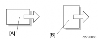
SEF | Short Edge Feed [A] |
LEF | Long Edge Feed [B] |
K | Black |
C | Cyan |
M | Magenta |
Y | Yellow |
B/W, BW | Black and White |
FC | Full color |

The following headings provide special information:
Failure to obey warning information could result in serious injury or death.
Obey these guidelines to ensure safe operation and prevent minor injuries.
Obey these guidelines to avoid problems such as misfeeds, damage to originals, loss of valuable data and to prevent damage to the machine.
Always obey these guidelines to avoid serious problems such as misfeeds, damage to originals, loss of valuable data and to prevent damage to the machine. Bold is added for emphasis.
This document provides tips and advice about how to best service the machine.
FAX OPTION M19 (D3DV) FOR D243/D244
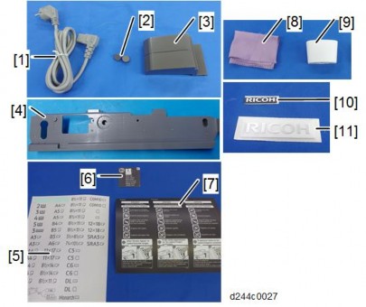
Check the quantity and condition of the accessories against the following list.
No. | Description | Q'ty | Remarks |
1 | Shield | 1 | |
2 | FCU | 1 | |
3 | Speaker Bracket | 1 | |
4 | Ferrite Core | 1 | For NA, this ferrite core is attached to the telephone cable. |
5 | Serial Number Decal | 1 | |
6 | Clamp | 2 | |
7 | FCU Screw: M3x6 | 4 | |
8 | Screw | 2 | Not used for this machine |
9 | Telephone Cable with ferrite core | 1 | NA only |
- | FCC Decal | 1 | NA only |
- | EMC Address Decal | 1 | EU Only |
- | Telephone Jack Cap | 1 | TWN only |

Before installing this fax unit, print out all data in the printer buffer. Turn the main power OFF and disconnect the power cord and the network cable.
Remove the I/F cover [A].

Remove the interface slot cover [A] ![]() x 2).
x 2).
Remove the "TEL" [A] and "LINE1" [B] covers on the interface slot cover using a screwdriver.
FAX OPTION M19 (D3DV) FOR D243/D244
Switch the battery jumper switch [A] to the "ON" position.
Connect the speaker bracket [A] to the FCU [B].

Attach the shield [A] to the FCU [B] and speaker bracket [C].

Insert the FCU [A] completely into the interface slot.

Reattach the interface slot cover [A].
Blue circle: Use the supplied screws (for the FCU)
Reinstall the I/F cover ![]() x 3).
x 3).
Attach the handset support bracket and handset bracket to the machine. To install the handset, connect the handset cord with the ferrite core to the "TEL" jack.
For details about installation, refer to "Handset (D645) (Link)".
Taiwan only: Install the telephone jack cap in the "TEL" jack if the handset is not installed on the machine.
Make one loop with the telephone cord, and then attach the ferrite core [A] (this step is not needed for NA).
FAX OPTION M19 (D3DV) FOR D243/D244
Connect the telephone cord to the "LINE 1" jack.
Attach the clamps [A] to the rear cover of the optional paper feed unit, and then hold the telephone line with the clamps as shown below.
Attach the serial number decal under the machine serial number decal on the rear cover of the machine.
Attach the FCC decal to the rear cover of the machine (NA only).
Insert the power plug into the outlet. Turn ON the main power of the machine.
Make sure that the outlet is grounded.
"SRAM formatted" is displayed on the operation panel after the main power is turned ON. Turn the main power OFF and then ON again for normal use.
Make sure that the date and time are correctly set.
Execute SP3-102-000 in the fax SP mode and enter the serial number for the fax unit.
Enter the correct country code with SP1101-016(SYS OF): Country/area code for functional setting.
Fax Stamp Installation
This procedure is needed only for machines with ARDF DF3090.
Open the ARDF original cover and stamp holder [A].
Install the fax stamp [A] provided with the machine.
Close the holder.
Make sure that the holder is pushed into the position where the marks on the holder and the exterior cover face each other. If not, jam detection (J001) will occur.
Close the ARDF.
As an operation test, place the original on ARDF tray, and send it with the memory sending/fax stamp function ON.
Set the sending time to a time when nobody uses the machine (such as 11 PM).
Check if the fax stamp is marked on the trailing edge of the original.
FAX OPTION M19 (D3DV) FOR D243/D244
The fax application icon is normally added automatically. However, if it is missing from the Home screen, add it as follows:
Press the [Application List] key [A].
Press and hold the Fax application from the app list.

Drag and position the application on the home screen.

Registering the Function key
By registering a fax application to a function key on the Home screen, you can open the application from any page. Specify the setting as required.
Function Keys 1, 2, and 3 are from the left, as shown:

Allocate an application to a function key as follows:
Login as the machine administrator
Press “User Tools” icon > “Screen Features”.
Press [Screen Device Settings].
Press [Function Key Settings].
FAX OPTION M19 (D3DV) FOR D243/D244
Select the key to register.
To disable a function key, deselect the corresponding function key check box.
Press [Allocated Function], and then select the fax application.

In [Display Name], you can change the name of the icon on the Home screen (using up to 64 characters).
Function Priority Setting
You can specify whether the fax application appears on the operation panel just after turning the power on or just after the system is reset automatically.
Login as the machine administrator
Press “User Tools” icon > “Screen Features”.
Press [Screen Device Settings].

