Scanning Sequence
Original Pick-up. The pick-up roller picks up the leading edge of original.
Original Feed and Separation. The feed belt and reverse roller feed the originals and prevent double-feeds.
Original size detection. 9 original size sensors, 5 for width and 4 for length, detect the original size on the original tray.
Original Scanning. A color CIS unit scans the reverse side of the originals (both sides are scanned in one pass).
SPDF DF3100 (D3B0)
Motors

No. | Part |
1 | Relay Motor |
2 | Entrance Motor |
3 | Feed Motor |
4 | Pick-up Motor |
5 | Tray Lift Motor |
6 | Exit Motor |
7 | Transport Motor |
Original Pick-up
Paper Feed
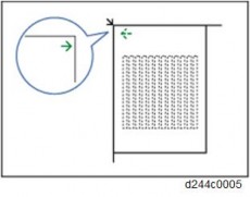
When an original is placed on the original tray, its leading edge raises the feeler of the original set sensor and the sensor detects the original.
Pick-up Roller
When there is no original on the original tray, the pick-up roller [C] swings up to the limit of its vertical movement.
To lower the pick-up roller, the pick-up roller motor [A] rotates the lift cam [E] which lowers the pick-up arm [D] and the pick-up roller.
When the pick-up roller is lowered, the pick-up roller motor [A] switches on.
When the actuator switches off the bottom plate position sensor [B], the pick-up roller motor goes off, and then the lift cam [E] holds the roller up.
Pick-up Roller Down Timing
The pick-up roller lowers:
When an original (or stack of originals) is set on the original table.
When the trailing edge of the original passes the sensor (but, it does not lower for the last original).
For A4/LT LEF when the leading edge reaches the registration sensor.
Pick-up Motor On/Off Timing
The pick-up motor switches ON:
When the original set sensor detects the leading edge of the original.
Just after the machine is turned on The pick-up motor switches OFF:
When the original feed cover is open.
When an original jams in the ADF paper path.
SPDF DF3100 (D3B0)
Bottom Plate Lift
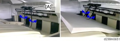
When an original is set on the original tray, after the pick-up roller drops, the bottom plate position sensor goes off, and then the plate lift motor [A] goes on and raises lift lever [B] which raises the bottom plate.
The actuator above the pick-roller holder switches on the bottom plate position sensor (see the previous diagram), and this turns the plate lift motor [A] off so the stack is positioned at the correct feed position.
During scanning with the ADF, when the top of the stack becomes too low, the pick-up roller drops low enough to turn the bottom plate position sensor off, which switches the lift motor [A] on again and raises the stack until once again it is at the paper feed position.
This mechanism performs continuously and keeps the top of the stack at the correct feed height for original stacks of up to 220 sheets (81.4 g/m2).

At the end of the job, the original table descends under its own weight as far as the bottom plate HP sensor [C].
Original Feed and Separation Mechanism
A feed belt [A] and ADF separation roller [C] comprise the FRR original separation mechanism.
If more than one original feeds between the nip of the feed roller and ADF separation roller, when the pick-up roller [B] picks up the front edge of the original, the rotation of the ADF separation roller [C] reverses immediately.

This sends the bottom sheet back into the tray while the sheet above continues to feed normally.
When more than one original feeds, this increases torque above the limit of the spring loaded torque limiter which reverses the rotation of the ADF separation roller against the rotation of the feed belt above.
The bottom sheet reverse feeds while the sheet above continues to feed into the paper path.
SPDF DF3100 (D3B0)
Skew Correction Mechanism
After the original feeds, the skew correction sensor detects its leading edge, and stops the rotation of the feed motor for a prescribed number of pulses.
The leading edge hits and straightens against the stationary roller to correct skew.
If the original is small (B6, A5, B5, HLT) (or when duplex scanning regardless of paper size), when the interval sensor [E] detects the leading edge of the original, it stops the pre-scanning roller [D] for a prescribed number of pulses, long enough for the original to buckle against the stationary roller and correct skew.

No. | Part |
A | Original Width Sensors |
B | Skew Correction Sensor |
C | Entrance Roller |
D | Scanning Entrance Roller |
E | Interval Sensor |
You can turn on SP6020-001 (ADF Contact Mode In/Out) to enable skew correction at both the entrance roller above as well as the pre-scanning roller below for all paper sizes but this may slow down the speed of original feeding.
Original Size Detection
When the leading edge of the original reaches the interval sensor, the machine determines the width from the readings of the 5 original width sensors.
The length of the original is determined by the readings of the 3 original length sensors under the original table and one sensor on the bottom plate.
These two arrays of sensors are used to determine the size of the originals.

No. | Part |
1 | Original Length Sensor A4/LT LEF |
2 | Original Length Sensor B5 |
3 | Original Length Sensor A4 |
4 | Original Length Sensor LG |
5 | Original Width Sensor 5 |
6 | Original Width Sensor 4 |
7 | Original Width Sensor 3 |
8 | Original Width Sensor 2 |
9 | Original Width Sensor 1 |
Size (W x L) | Width Sensors | Length Sensors | |||||||
1 | 2 | 3 | 4 | 5 | A4 LEF | B5 | A4 | LG | |
A3(297x420) | ON | ON | ON | ON | ON | ON | ON | ON | ON |
B4(257x364) | ON | ON | ON | --- | --- | ON | ON | ON | ON |
A4 SEF (210x297) | ON | ON | --- | --- | --- | ON | ON | ON | - |
A4 LEF (297x210) | ON | ON | ON | ON | ON | --- | --- | --- | --- |
A4 SEF (210x297) | ON | --- | --- | --- | --- | ON | ON | --- | --- |
A4 LEF (297x210) | ON | ON | ON | --- | --- | --- | --- | --- | --- |
A4 SEF (210x297) | --- | --- | --- | --- | --- | --- | --- | --- | --- |
A4 LEF (297x210) | ON | --- | --- | --- | --- | --- | --- | --- | --- |
DLT SEF (11"x17") | ON | ON | ON | ON | --- | ON | ON | ON | ON |
DLT SEF (11"x17") | ON | ON | ON | ON | --- | ON | ON | ON | ON |
8 1/2"x11" SEF (LT) | ON | ON | --- | --- | --- | ON | ON | --- | --- |
11"x8 1/2" LEF (LT) | ON | ON | ON | ON | --- | --- | --- | --- | --- |
SPDF DF3100 (D3B0)
11"x17" and 11"x15" are detected as the same size, so you need to select one or the other with SP6016-001 (Original Size Determination Priority) to choose whichever you are using.
Original Transport
At the beginning of the job, the original feed motor switches on and rotates the pick-up roller, feed belt, and reverse roller to feed the original into the original feed path.
The original is fed to the entrance roller as it leaves the original tray. Original skew is corrected at the entrance roller.

No. | Part |
A | Feed Motor |
B | Feed Belt |
C | Pick-up Roller |
D | ADF Separation Roller |
E | Entrance Roller |
F | Separation Sensor |
After skew is corrected at the entrance roller, the entrance motor [G] and transport motor [H] rotate the rollers in the original path and feed the original to the scanning section below.

No. | Part |
G | Entrance Motor |
H | Relay Motor |
I | Transport Roller |
SPDF DF3100 (D3B0)
When the interval sensor [M] detects the original, the transport motor [K] turns on and rotates the white roller [J] and feeds the original through the scan unit.
After rotation of the entrance roller, the entrance motor speeds up slightly to reduce the gap between the trailing edge of the original in the scanning unit and the leading edge of the next original in the path.
If this were allowed to continue, the differences in roller rotation speed could cause the originals to bend or buckle in the original path around the pre-scanning roller.
To avoid this, when the interval sensor detects the leading edge of an original it slows the rotation of the scanning belt and the speed of the original in the nip of the pre-scanning roller slows.

When the original exit sensor [Q] detects the leading edge of the original, the exit motor [P] switches on and rotates the exit roller [O] which feeds the original out onto the original output tray.

SPDF DF3100 (D3B0)
Original Scanning
This machine has a color CIS (Contact Image Sensor) so that it scan both sides of an original at the same time.

No. | Part |
A | ADF |
B | White Roller |
C | Scanner LEDs (Exposure Lamps) |
Jam Detection

No. | Part |
1 | Skew Correction Sensor |
2 | Separation Sensor |
3 | Original Exit Sensor |
4 | Registration Sensor |
5 | Interval Sensor |
SPDF DF3100 (D3B0)
Jams are detected by the 5 sensors listed above. The detection conditions are shown in the table below.

Jam Display | Jam Name | Detection Condition |
P1 | Separation sensor late jam | Feed motor on but leading edge failed to arrive after motor on long enough to feed 224 mm. |
P1 | Skew correction sensor late jam | Leading edge failed to arrive after separation sensor detection and enough time elapsed for the original to feed 46 mm. |
P1 | Interval sensor late jam | Leading edge failed to arrive after entrance motor started and remained on long enough for the original to feed 172 mm. |
P! | Registration sensor late jam | Original failed to arrive after it was detected by the interval sensor and enough time elapsed for the original to feed 96 mm. |
P2 | Original exit sensor late jam | Original failed to arrive after it was detected by the registration sensor and enough time elapsed for it to feed 130 mm. |
P1 | Separation sensor lag jam | After the entrance roller started to pull the original out of the original tray after initial feeding, the original failed to move based on the calculations below. |
A4/LT | L1 | L2 | L3 | Std. | |
Not | Not | Not | Not | 226.8 | |
Detected | Not | Not | Not | 253.8 | |
- | Detected | Not | Not | 291 | |
- | - | Detected | Not | 320 | |
- | - | - | Detected | 432 | |
However, in some cases the operator may have specified another length longer than the standard value and that value will be used as standard (Std.). | |||||
P1 | Skew correction sensor lag jam | After the separation sensor detected the trailing edge, the trailing edge was still detected after enough time had elapsed for the original to feed 46 mm. | |||
P! | Interval sensor lag jam | After the transport motor turned on, the trailing edge of the original was not detected after enough time had elapsed for the original to feed 82 mm. | |||
P2 | Registration sensor lag jam | After the interval sensor detected the trailing edge, the trailing edge was still detected after enough time had elapsed for the original to feed 93 mm. | |||
P2 | Original exit sensor late lag | After the registration sensor detected the trailing edge, the trailing edge was still detected after enough time had elapsed for the original to feed 130 mm. | |||
SPDF DF3100 (D3B0)
SC | Error Name | Probable Cause |
700-01* | ADF bottom plate lift motor error | |
700-02* | ADF original pick-up motor error | |
700-04* | ADF feed motor error | |
700-05* | ADF entrance motor error | |
700-06* | ADF transport motor error |
No output from bottom plate position sensor
No output from bottom plate HP sensor
Bottom plate motor not operating
ADF main board problem
No signal from the pickup HP sensor because sensor harness, connector loose, broken, defective.
Pick-up HP sensor defective
Pick-up motor harness, connector, is loose, broken, defective.
Pick-up motor defective.
ADF main board defective
Paper jammed in paper path
Motor overload due to blockage
Motor harness loose, broken, defective
Motor bracket, motor installed incorrectly
Feed motor defective
Paper jammed in paper path
Motor overload due to blockage
Motor harness loose, broken, defective
Motor bracket, motor installed incorrectly
Entrance motor defective
Paper jammed in paper path
Motor overload due to blockage
Motor harness loose, broken, defective
Motor bracket, motor installed incorrectly
Transport motor defective
SC | Error Name | Probable Cause |
700-07* | ADF Scanning Motor | |
700-09* | ADF exit motor error | |
702-04 | ADF protection circuit error 4 | |
702-05 | ADF protection circuit error 5 | |
151-00 | Black level error: Back side | |
152-00 | White level error: Back side | |
154-00 | Scanner communication error: Back side |
Paper jammed in paper path
Motor overload due to blockage
Motor harness loose, broken, defective
Motor bracket, motor installed incorrectly
Scanning motor defective
Paper jammed in paper path
Motor overload due to blockage
Motor harness loose, broken, defective
Motor bracket, motor installed incorrectly
Exit motor defective
Defective motor or harness on the interlock circuit.
Interlock power circuit harness, switch is loose, broken, defective.
Motor harness, connector is loose, broken, or defective.
Motor is defective.
CIS defective
ADF CIS device defective
CIS white roller background or white plate damaged
CIS dirty or installed incorrectly
Harness between the ADF PCB and CIS is loose, broken, defective
ASIC in CIS is defective
FROM in CIS is defective
*The machine issues a jam alert for first two occurrences, and then issues the SC code at the third occurrence. To recover, cycle the machine off/on.
SPDF DF3100 (D3B0)
To improve the alignment of the delivered originals, select to give priority to stackability in the following SP. This will reduce the originals’ delivery speed and improve their stackability.
SP6-901-001 (Setting to give priority to stackability): for DF3100 0: Higher throughput (default)
1: Higher stackability
R EVI SIO N HIS TORY | ||
Page | Date | Added/ Updated/ New |
None | ||
EXTERIOR PARTS 1
FRONT COVER 1
INNER COVER 2
REAR COVER 4
FRONT LEFT COVER 4
UPPER COVER 5
UPPER FRONT COVER 6
UPPER REAR COVER 7
PAPER EXIT GUIDE COVER 8
UPPER LEFT COVER 9
PROOF TRAY 9
SHIFT TRAY 10
BOOKLET TRAY (SR3220) 10
LEFT CENTER COVER 11
LEFT LOWER COVER 12
MAIN UNIT 13
PAPER EXIT GUIDE PLATE OPEN/CLOSE MOTOR 13
PAPER EXIT GUIDE PLATE OPEN/CLOSE HP SENSOR 13
PROOF TRAY FULL SENSOR 14
PROOF TRAY PAPER EXIT SENSOR 15
ENTRANCE SENSOR 16
INTERMEDIATE TRANSPORT SENSOR RIGHT 16
INTERMEDIATE TRANSPORT SENSOR LEFT 17
SHIFT TRAY PAPER SURFACE SENSOR 18
SHIFT TRAY UPPER LIMIT SWITCH 19
SHIFT TRAY PAPER EXIT SENSOR 19
PAPER EXIT GUIDE HP SENSOR 20
ENTRANCE TRANSPORT MOTOR 20
PROOF TRANSPORT MOTOR 21
SM i D3B8/D3B9
POSITIONING ROLLER MOTOR 21
SHIFT MOTOR 23
PAPER EXIT TRANSPORT MOTOR 23
PAPER EXIT GUIDE DRIVE MOTOR 25
PAPER BUNDLE TRANSPORT UPPER MOTOR (SR3220) 26
STAPLER TRAY 28
STAPLER TRAY PAPER SENSOR 30
PAPER BUNDLE TRANSPORT UPPER PRESSURE RELEASE HP SENSOR 31 1.2.22 FEEDOUT PAWL HP SENSOR 31
JOGGER HP SENSOR 32
JOGGER MOTOR 32
PAPER BUNDLE TRANSPORT UPPER PRESSURE RELEASE MOTOR 33
FEEDOUT PAWL MOTOR 34
STAPLELESS STAPLER UNIT/STAPLER UNIT (SR3210) 35
STAPLELESS STAPLER UNIT 35
STAPLER UNIT 36
STAPLELESS STAPLER TRANSFER MOTOR 38
STAPLER TRANSFER MOTOR 38
PAPER GUIDE DRIVE MOTOR 39
STAPLELESS STAPLER HP SENSOR 40
STAPLER HP SENSOR 41
PAPER GUIDE HP SENSOR 42
BOOKLET STAPLER UNIT (SR3220) 43
STAPLER UNIT 43
BOOKLET STAPLER UNIT 49
CENTER-FOLDING UNIT 50
CENTER-FOLDING TRAY PAPER EXIT SENSOR 52
TRAILING EDGE STOPPER TRANSPORT SENSOR 53
TRAILING EDGE STOPPER HP SENSOR 54
CENTER-FOLDING BLADE HP SENSOR 54
CENTER-FOLDING CAM HP SENSOR 55
TRAILING EDGE STOPPER MOTOR 56
FOLDING BLADE MOTOR 56
FOLDING TRANSPORT MOTOR 57
BOOKLET TRAY FULL SENSOR 1, 2 58
STAPLER TRANSFER MOTOR (MIDDLE) 59
PAPER BUNDLE TRANSPORT LOWER PRESSURE RELEASE HP SENSOR60 1.5 BOARDS 61
1.5.1 MAIN CONTROLLER BOARD 61
BOOKLET FINISHER SR3220 / FINISHER SR3210 (D3B9/D3B8) 63
CHANGES FROM THE PREVIOUS MACHINE 63
Paper exit guide 63
Stapleless Stapler (Finisher SR3210 only) 65
SP6-160-004 (Replacement Mode for Service) 75
PARTS LAYOUT 76
Drive layout 77
Electrical component layout 79
MECHANISMS 86
Separation mechanism 86
Proof tray transport 86
Proof tray full detection 87
Shift tray ascent/descent mechanism 87
Shift tray full detection 88
Shift mechanism 89
Booklet tray 90
Stapled paper eject mechanism 91
Booklet stitching mechanism 98
2.2 PUNCH UNIT PU3050 (D717) 101
CHANGES FROM THE PREVIOUS MACHINE 101
PARTS LAYOUT 102
MECHANISM 102
Skew Correction 103
Registration 103
Punch hole alignment adjustment 104
Paper position detection 105
Punch unit movement 105
Punch drive 106
Punch scrap collection/full detection 107
SM iii D3B8/D3B9
This manual uses several symbols and abbreviations. The meaning of those symbols and abbreviations are as follows:
Symbol | What it means |
| Clip ring |
| Screw |
| Connector |
| Clamp |
| E-ring |
| Flat Flexible Cable |
| Timing Belt |
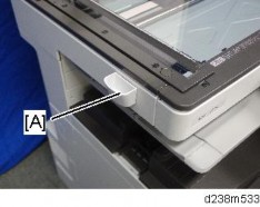
SEF | Short Edge Feed [A] |
LEF | Long Edge Feed [B] |
K | Black |
C | Cyan |
M | Magenta |
Y | Yellow |
B/W, BW | Black and White |
FC | Full color |

Adobe, Acrobat, PageMaker, PostScript, and PostScript 3 are either registered trademarks or trademarks of Adobe Systems Incorporated in the United States and/or other countries.
The Bluetooth® word mark and logos are registered trademarks owned by Bluetooth SIG, Inc. and any use of such marks by Ricoh Company, Ltd. is under license.
Firefox and Thunderbird are registered trademarks of the Mozilla Foundation. Google, Android, and Chrome are trademarks of Google Inc.
iOS® is a registered trademark or trademark of Cisco Systems, Inc. and/or its affiliates in the United States and certain other countries.
Java is a registered trademark of Oracle and/or its affiliates.
JAWS® is a registered trademark of Freedom Scientific, Inc., St. Petersburg, Florida and/or other countries.
Kerberos is a trademark of the Massachusetts Institute of Technology (MIT). Linux is a registered trademark of Linus Torvalds.
Macintosh, OS X, Bonjour, Safari, and TrueType are trademarks of Apple Inc., registered in the
U.S. and other countries.
Microsoft, Windows, Windows Server, Windows Vista, Internet Explorer, and Outlook are either registered trademarks or trademarks of Microsoft Corp. in the United States and/or other countries.
PictBridge is a trademark.
QR Code is a registered trademark of DENSO WAVE INCORPORATED in Japan and in other countries.
"Red Hat" is a registered trademark of Red Hat, Inc. The SD and SD logo are trademarks of SD-3C, LLC. UNIX is a registered trademark of The Open Group.
UPnP is a trademark of UPnP Implementers Corporation.

This product includes RSA BSAFE® Cryptographic software of EMC Corporation. RSA and BSAFE are registered trademarks or trademarks of EMC Corporation in the United States and other countries.
The proper names of Internet Explorer 6, 7, and 8 are as follows:
Microsoft® Internet Explorer® 6
Windows® Internet Explorer® 7
Windows® Internet Explorer® 8
The proper names of the Windows operating systems are as follows:
The product names of Windows Vista are as follows: Microsoft® Windows Vista® Ultimate
Microsoft® Windows Vista® Business Microsoft® Windows Vista® Home Premium Microsoft® Windows Vista® Home Basic Microsoft® Windows Vista® Enterprise
The product names of Windows 7 are as follows: Microsoft® Windows® 7 Home Premium Microsoft® Windows® 7 Professional
Microsoft® Windows® 7 Ultimate Microsoft® Windows® 7 Enterprise
The product names of Windows 8 are as follows: Microsoft® Windows® 8
Microsoft® Windows® 8 Pro Microsoft® Windows® 8 Enterprise
The product names of Windows 8.1 are as follows: Microsoft® Windows® 8.1
Microsoft® Windows® 8.1 Pro Microsoft® Windows® 8.1 Enterprise
The product names of Windows 10 are as follows: Microsoft® Windows® 10 Home Premium Microsoft® Windows® 10 Pro
Microsoft® Windows® 10 Enterprise Microsoft® Windows® 10 Education
The product names of Windows Server 2003 are as follows: Microsoft® Windows Server® 2003 Standard Edition Microsoft® Windows Server® 2003 Enterprise Edition
The product names of Windows Server 2003 R2 are as follows: Microsoft® Windows Server® 2003 R2 Standard Edition Microsoft® Windows Server® 2003 R2 Enterprise Edition
The product names of Windows Server 2008 are as follows:
Microsoft® Windows Server® 2008 Standard Microsoft® Windows Server® 2008 Enterprise
The product names of Windows Server 2008 R2 are as follows: Microsoft® Windows Server® 2008 R2 Standard
Microsoft® Windows Server® 2008 R2 Enterprise
The product names of Windows Server 2012 are as follows: Microsoft® Windows Server® 2012 Foundation
Microsoft® Windows Server® 2012 Essentials Microsoft® Windows Server® 2012 Standard
The product names of Windows Server 2012 R2 are as follows: Microsoft® Windows Server® 2012 R2 Foundation
Microsoft® Windows Server® 2012 R2 Essentials Microsoft® Windows Server® 2012 R2 Standard
Other product names used herein are for identification purposes only and might be trademarks of their respective companies. We disclaim any and all rights to those marks.
Microsoft product screen shots reprinted with permission from Microsoft Corporation.
Exterior Parts
FINISHER SR3210/ BOOKLET FINISHER SR3220 (D3B8/D3B9)
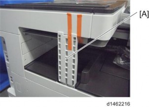
Open the front cover [A].

Front cover [A] ![]() ×1)
×1)

SM 1 D3B8/D3B9
Open the front cover (page 1 "Front Cover")
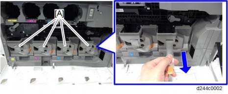
Remove the three knobs [A] (hook×1 for each).
Use a flathead screwdriver to release the hooks.

Remove the three screws on the inner cover [A] ![]() ×3).
×3).

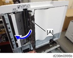
Pull the booklet stapler unit [A].
Inner cover [B] ![]() ×1)
×1)
D3B8/D3B9
3
SM
Exterior Parts

FINISHER SR3210/ BOOKLET FINISHER SR3220 (D3B8/D3B9)
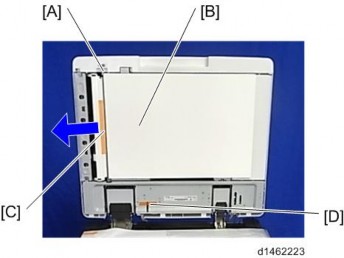
1. Rear cover [A] ![]() ×3)
×3)

Front cover (page 1)
Inner cover (page 2)
Paper exit guide cover (front) (page 8 "Paper Exit Guide Cover")
Front left cover [A] ![]() ×2)
×2)

FINISHER SR3210/ BOOKLET FINISHER SR3220 (D3B8/D3B9)
Open the upper cover [A].

Upper cover [A] ![]() ×1, tab ×1)
×1, tab ×1)
When reattaching the upper cover, attach the clips so that their tabs face upward.

Front left cover (page 4)
Upper cover (page 5)
Upper front cover [A] ![]() ×3)
×3)

Rear cover (page 4)
Paper exit guide cover (page 8)
Upper left cover (page 9)
FINISHER SR3210/ BOOKLET FINISHER SR3220 (D3B8/D3B9)
Upper cover (page 5)
Upper rear cover [A] ![]() ×3)
×3)

Paper exit guide cover (front) [A]
Paper exit guide cover (rear) [B] ![]() ×4)
×4)
If the view of the screw hole is obstructed by the paper exit guides [C], hold the paper exit guides on the sides and move them inward.

Paper exit guide cover (page 8)
FINISHER SR3210/ BOOKLET FINISHER SR3220 (D3B8/D3B9)
Upper left cover [A] ![]() ×2)
×2)
Upper front cover (page 6)
Upper rear cover (page 7)
Proof tray [A] ![]() ×2)
×2)

1. Shift tray [A] ![]() ×1)
×1)

1. Booklet tray [A]

Front cover (page 1)
Rear cover (page 4)
Shift tray (page 10)
FINISHER SR3210/ BOOKLET FINISHER SR3220 (D3B8/D3B9)
Shift tray front bracket [B] ![]() ×2)
×2)
Shift tray bracket [A] with the shift tray rear bracket [C]
Left center cover [A] ![]() ×2)
×2)
For SR3220
Booklet tray (page 10)
Left lower cover [A] ![]() ×2)
×2)
For SR3210
1. Left lower cover [A] ![]() ×2)
×2)

FINISHER SR3210/ BOOKLET FINISHER SR3220 (D3B8/D3B9)
Proof tray (page 9)
Paper exit guide plate open/close motor [A] ![]() ×2,
×2, ![]() ×1)
×1)
Proof tray (page 9)
Paper exit guide plate HP sensor [A] ![]() ×1,
×1, ![]() x1)
x1)
Proof tray (page 9)
Proof tray full sensor [A] ![]() ×1,
×1, ![]() ×1)
×1)
Inner cover (page 2)
Proof tray (page 9)
FINISHER SR3210/ BOOKLET FINISHER SR3220 (D3B8/D3B9)
Proof transport bracket [A] ![]() ×4)
×4)
Proof tray paper exit sensor [A] ![]() ×1,
×1, ![]() ×1)
×1)
1. Entrance sensor [A] ![]() ×1,
×1, ![]() ×1,
×1, ![]() ×1)
×1)
Upper cover (page 5)
Intermediate transport sensor right [A] ![]() ×1,
×1, ![]() ×1,)
×1,)
Proof tray (page 9)
FINISHER SR3210/ BOOKLET FINISHER SR3220 (D3B8/D3B9)
Intermediate transport sensor left [A] ![]() ×1,
×1, ![]() ×1,
×1, ![]() ×1)
×1)
Left center cover (page 11)
Bracket [A] ![]() ×4)
×4)
Shift tray paper surface sensor [A] ![]() ×1,
×1, ![]() x1)
x1)
Bracket of the shift tray (page 18 "Shift Tray Paper Surface Sensor")
FINISHER SR3210/ BOOKLET FINISHER SR3220 (D3B8/D3B9)
Shift tray upper limit switch [A] ![]() x2, hook × 1)
x2, hook × 1)

Left center cover (page 11)
Shift tray paper exit sensor [A] (hook ×1, ![]() x1,
x1, ![]() ×1)
×1)
Upper left cover (page 9)
Paper exit guide HP sensor with bracket [A] ![]() ×1)
×1)
Paper exit guide HP sensor [A] ![]() ×1, hook ×2 )
×1, hook ×2 )
Rear cover (page 4)
Entrance transport motor [A] ![]() ×2,
×2, ![]() ×1)
×1)
Rear cover (page 4)
FINISHER SR3210/ BOOKLET FINISHER SR3220 (D3B8/D3B9)
Proof transport motor [A] ![]() ×2,
×2, ![]() ×1)
×1)
For SR3220
Rear cover (page 4)
Positioning roller motor [A] ![]() ×2,
×2, ![]() ×1)
×1)
For SR3210
Rear cover (page 4)
Move the harness guide [A] to the right. ![]() ×2)
×2)
Positioning roller motor [A] ( ×2,
×1)
3.
Rear cover (page 4)
Paper exit guide cover (rear) (page 8 "Paper Exit Guide Cover")
FINISHER SR3210/ BOOKLET FINISHER SR3220 (D3B8/D3B9)
Shift motor [A] ![]() ×2,
×2, ![]() x1)
x1)

For SR3220
Rear cover (page 4)
Paper exit transport motor [A] ![]() ×2,
×2, ![]() ×1)
×1)
For SR3210
Rear cover (page 4)
Harness guide [A] ![]() ×2,
×2, ![]() ×6)
×6)

Paper exit transport motor [A] ![]() ×2,
×2, ![]() ×1)
×1)