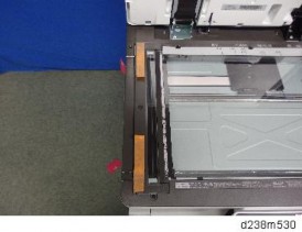
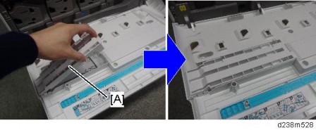
Remove the sheet-through exposure glass [A]

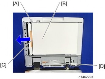
Remove the rear scale [A]
Remove the left scale and exposure glass [A]
The exposure glass and the left scale are attached with double-sided tape.

Move the scanner carriage to the right.
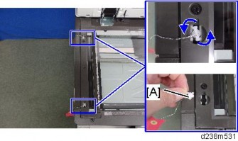
Attach the heater [B] to the bracket [A] provided with the accessories ![]() × 2).
× 2).

Remove the release paper [A] on the back side of the bracket, and secure the heater
[B] with the seal, aligning it with the boss on the frame.

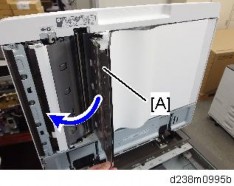
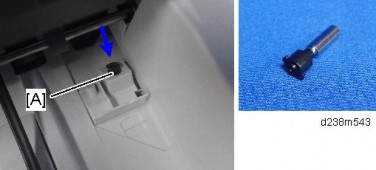
Pull the harness [A] out of the frame hole.
Route the harness into the harness guide.
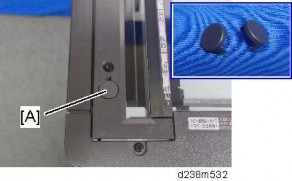
Attach the heater cover [A] ( × 1).


Connect the heater harness that was pulled out of the frame hole to the connector which was mounted in step 15.
Reattach all the removed covers.
This option is provided as a service part.
If you want to install Anti-Condensation Heater (PCDU), electrical parts (1) and heater for PCDU (2) should be ordered.
Electrical parts
Description | Q’ty | Remarks |
TAPPING SCREW M3X6 | 3 | Parts Number: |
D2386650 | ||
CLAMP | 6 | |
Electrical parts set for Scanner and | ||
HARNESS: SCANNER/PCU | 1 | Drum heater is common between |
NA/EU | ||
PCB: DHB | 1 | |
HARNESS :DC: DHB | 1 | |
HARNESS :AC: DHB | 1 |
Heater for PCDU
Description | Q’ty | Remarks |
TAPPING SCREW: WASHER M3X8 | 1 | Parts Number: |
HEATER: PHOTOCONDUCTOR: EU HEATER: PHOTOCONDUCTOR: NA | 1 | |
DECAL HIGHT TEMP | 1 |
NA (120V): D7390116
EU/AA (220/240V): D7390117
Remove the rear cover [A].

Remove the rear lower cover [A].

Remove the power supply box [A] ![]() x6, Among them, tapping screw x1)
x6, Among them, tapping screw x1)

Release the 5 clamps.

Remove the HVP-CB with bracket [A] (Hook x2).


Connect the combined Blue/White harness to the back frame [A].

The harness will be connected to the relay board. See the details in step 8.
Reinstall the HVP-CB unit and power supply box.

Secure the relay board to the main machine and connect the Blue/White harness to the socket on the board ![]() × 1,
× 1, ![]() × 3).
× 3).
Connect the harnesses on the relay board to the sockets on the PSU.
Two types of harnesses are packed with the heater. Both the Blue/White one [A] and the Gray one [B] must be connected as shown below.

Remove the right rear cover [A] ![]() x4, among them, tapping screw x1)
x4, among them, tapping screw x1)

Remove a screw.

Remove the scanner right cover [A].
Remove the hook at the upper part, and then slide the cover in the rear direction.

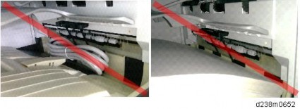
Route the harness around the outside of the PSU and pull the harness out of the electrical box through the hole [A] ![]() x 4).
x 4).

Route the harness in the direction of the scanner ![]() x 6).
x 6).


Fasten the clamp between the bindings of the harness at the location indicated by the red circle.
Attach the connector to the frame.

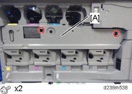
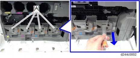
Remove Feed Trays 1 and 2.
The connecter cover located inside the machine [A] ![]() × 1).
× 1).

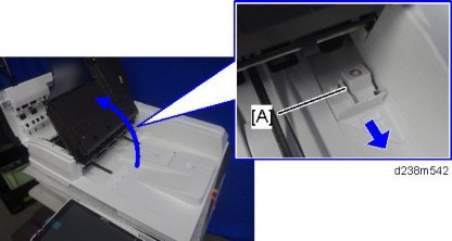
Temporarily tighten a screw at the top ![]() M3x8: x1).
M3x8: x1).

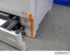
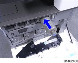
Install the heater [A] by connecting the connector to the inside of the machine, then tighten the screw completely.
Hold the heater against the inside during final tightening.

Reinstall the connector cover ![]() × 1).
× 1).
Attach the warning decal [A].

Reassemble the machine.
Connect the power cord, and then check that the heater is being powered and heated.
Unplug the machine power cord before starting the following procedure.
Do the following procedure not to damage any harnesses.
Check that harnesses are not damaged or pinched after installation.
Anti-Condensation Heater (Service Option) for Main Machine
No. | Description | Q’ty | Remarks |
1 | Tray heater | 1 | Heater and harness |
Parts Number: | |||
2 | Tapping screw: M3 X 8 | 2 | |
3 | PCB: DHB | 1 | Electrical components |
Parts Number: | |||
4 | Harness for tray | 1 | |
5 | Harness for DC | 1 | |
*D2386660 | |||
6 | Harness for AC | 1 | |
7 | Tapping screw: M3 X 6 | 3 |
NA (120V): D2386630
EU/AA (220/240V): D2386640
NA (120V): D2386661, *D2386660
EU/AA (220/240V): D2386662,
*: Old parts number
Anti-Condensation Heater (Service Option) for Optional Paper Feed Unit
No. | Description | Q’ty | Remarks |
1 | Tray heater | 1 | Heater and harness |
Parts Number: | |||
2 | Harness | 1 | |
3 | Spring screw:M4 X 10 | 3 | |
Those parts number is common with MP | |||
C2003/C2503. |
NA (120V): D6931117
EU/AA (220/240V): D6931127
Remove the rear cover [A].

Remove the rear lower cover [A].

Attach PCB: DHB ![]() X 3).
X 3).

Connect the two harnesses between "PCB: DHB" and "PSU".

Red dashed circled cable is only white for NA, red for EU/AA.
Connect connector 1.
Connect connector 2 to the harness already attached.
Attach connector 3 for the optional paper bank.

This cable is only white for NA/EU/AA.
Remove trays 1 and 2 from the machine.

Connect the connector of the heater to the main machine.

Install the heater inside the machine ![]() x 1).
x 1).

Reattach trays 1 and 2.
Perform Steps 1 to 7 of page 2-59 "Connecting to Main Machine Tray".
Pull out the 1st and 2nd paper feed trays of the paper feed unit.

Pass the harness of the heater [A] for the optional paper feed unit through the hole in the inner rear frame of the optional paper feed unit, and then attach it ![]() x1).
x1).
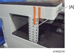
Remove the securing brackets [A] of the optional paper feed unit.
Remove the rear cover [A] of the optional paper feed unit.

Remove the bracket [A] on the bottom of the main unit ![]() x1).
x1).
The removed bracket can be discarded.
Connect the PFU harness [A] of the optional paper feed unit to the relay harness [B] of the main unit and the heater harness [C] ![]() x4).
x4).
Reinstall the removed parts and covers.
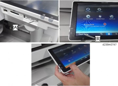
Connect the power supply cord and turn ON the main power.
Do the following two steps to set the anti-condensation heater to be constantly ON.
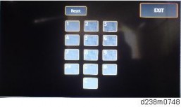
Set the setting of SP5-805-001 (Anti-Condensation Heater ON/OFF setting) to [1].
Manually disconnect the PCU and scanner heaters.
The PCU and scanner heaters must be disabled because the temperature in the machine could become too high, causing problems with toner clogging, or damage to the scanner lamp stabilizer
Perform Steps 1 to 7 of page 2-59 "Connecting to Main Machine Tray".
Pull out the paper feed tray of PB3150.
Put the harness of the heater [A] for the optional paper feed unit through the hole at the inner rear frame, and then attach it ![]() x1).
x1).

Remove the securing brackets [A] of Paper Feed Unit PB3150.

Remove the rear cover [A] of Paper Feed Unit PB3150.

Remove the bracket [A] on the bottom of the main unit ![]() x1).
x1).
The removed bracket can be discarded.
Connect the PFU harness [A] of the optional paper feed unit to the relay harness [B] of the main unit and the heater harness [C] ![]() x4).
x4).
Reinstall the removed parts and covers.
Connect the power supply cord and turn ON the main power.
Do the following two steps to set the anti-condensation heater to be constantly ON.
Set the setting of SP5-805-001 (Anti-Condensation Heater ON/OFF setting) to [1].
Manually disconnect the PCU and scanner heaters.
The PCU and scanner heaters must be disabled because the temperature in the machine could become too high, causing problems with toner clogging, or damage to the scanner lamp stabilizer
No. | Description | Q’ty | Remarks |
1 | Screws (M4 × 10) | 2 | |
2 | Screw with Spring Washer (M4 × 10) | 1 | |
3 | Securing Bracket | 2 |

The main machine weighs approximately 100 kg. Make sure to lift it with the help of at least one more person.
The machine should be held at the correct locations and lifted gently. If it is lifted without care, handled carelessly or dropped, it may result in an injury.
When installing this option, turn OFF the main power and unplug the power cord from the wall socket. If installing without turning OFF the main power, an electric shock or a malfunction may occur.
Be sure to join the machine to the paper feed unit so as to prevent equipment from falling over. If they are not connected, they may move and fall over, resulting in injury.
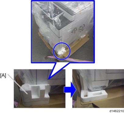
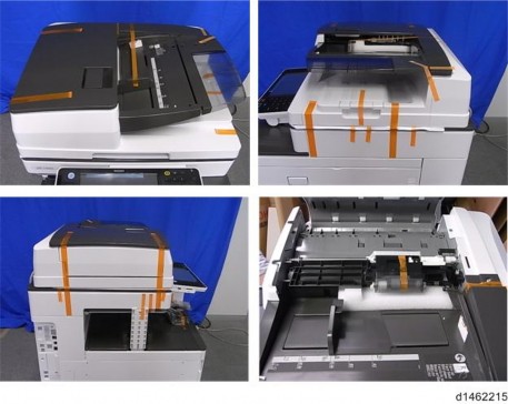
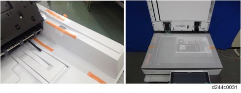
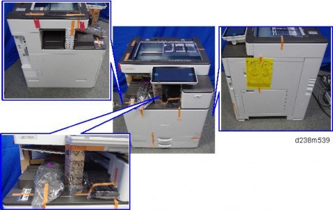
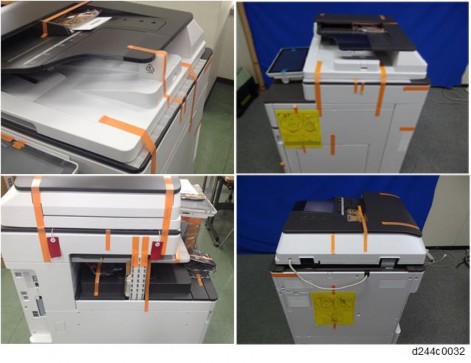
Remove the orange tapes and retainers.
Remove the accessories (fixing screws, etc.) (provided with the machine) from the package.
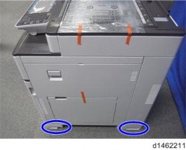
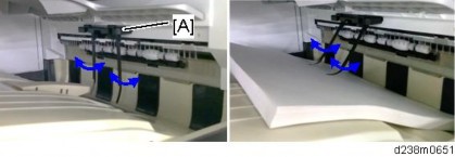
Holding the grips on the machine, align the machine with the locating pins [A], and place the machine on the paper feed unit.
When you lift the machine, hold the correct locations.

Do not hold any other parts of the machine when lifting it, because this may cause the machine to deform.
Do not put the machine down on the paper feed unit as a temporary resting place. This may cause the paper feed unit to deform. Always connect the machine and paper feed unit properly.
Pull out the 2nd paper feed tray.
Using a securing bracket as a screwdriver, fix the machine to the feed unit (spring washer: screw: M4×10: 1).
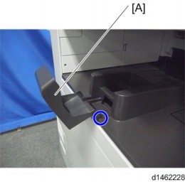
Attach the securing brackets [A] to two positions on the left and right at the rear of the machine (screws: 1 each).

Reattach the paper feed tray to the machine
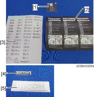
Attach the decals as shown below.
[A]: Tray number decal [B]: Paper size decal
The tray number decal and paper size decal are packaged together with the machine.
Lock the casters of the paper feed unit.
Connect the power cord to the machine.
Stabilizers are attached to the machine when it is shipped. Do not remove them.
Turn ON the main power.
Set the paper, and check that the paper size set in the paper feed tray is displayed on the operation panel.
Adjust the registration for the paper feed unit.
SP1-002-004 (Side-to-Side Registration Paper Tray 3)
SP1-002-005 (Side-to-Side Registration Paper Tray 4)
SP descriptions
SP1-002 (Side-to-Side Registration)
Adjusts the side-to-side registration by changing the laser main scan start position for each mode and tray.
Increasing a value: The image is moved towards the rear edge of the paper. Decreasing a value: The image is moved towards the front edge of the paper.
No. | Descriptions | Q’ty | Remarks |
1 | Securing Bracket | 2 | |
2 | Screws - M4 × 10 | 2 | |
3 | Screw with Spring Washer - M4 × 10 | 1 |
The main machine weighs approximately 100 kg. Make sure to lift it with the help of at least one more person.
The machine should be held at the correct locations and lifted gently by two people. If it is lifted without care, handled carelessly or dropped, it may result in injury.
When installing this option, turn OFF the main power and unplug the power cord from the wall socket. If installing without turning OFF the main power, an electric shock or a malfunction may occur.
Be sure to join the machine to the paper feed unit so as to prevent equipment from falling over. If they are not connected, they may move and fall over, resulting in injury.
Paper Feed Unit PB3150 is not supplied with a caster. You can attach the optional page 2-76 "Caster Table Type M3 (D178)".
Remove the orange tapes and retainers.
Remove the accessories (fixing screws, etc.) (provided with the machine) from the package.
Holding the grips on the machine, align the machine with the locating pins [A], and place the machine on the paper feed unit.

When you lift the machine, hold the correct locations.
Do not hold any other parts of the machine when lifting it, because this may cause the machine to deform.
Do not put the machine down on the paper feed unit as a temporary resting place. This may cause the paper feed unit to deform. Always connect the machine and paper feed unit properly.
Pull out the 2nd paper feed tray.
Using a securing bracket as a screwdriver, fix the machine to the feed unit (spring washer: screw: M4×10: 1).
Attach the securing brackets [A] to two positions on the left and right at the rear of the machine (screws: 1 each).
Reattach the paper feed tray to the machine.
Attach the decals as shown below.

[A]: Tray number decal [B]: Paper size decal
The tray number decal and paper size decal are packaged together with the machine.
Connect the power cord to the machine.
Turn ON the main power.
Set the paper, and check that the paper size set in the paper feed tray is displayed on the operation panel.
Adjust the registration for the paper feed unit.
SP1-002-004 (Side-to-Side Registration Paper Tray 3)
SP descriptions
SP1-002 (Side-to-Side Registration)
Adjusts the side-to-side registration by changing the laser main scan start position for each mode and tray.
Increasing a value: The image is moved towards the rear edge of the paper. Decreasing a value: The image is moved towards the front edge of the paper.
No. | Description | Q’ty | Remarks |
1 | Right Lower Cover | 1 | Not used when Paper Feed Unit PB3150 is installed. |
2 | Securing Bracket | 2 | |
3 | Screws (M4 × 10) | 2 | |
4 | Screw with Spring Washer (M4 × 10) | 1 |

The main machine weighs approximately 100 kg. Make sure to lift it with the help of at least one more person.
The machine must be held at the correct locations, and must be lifted slowly. If it is lifted with force, handled carelessly or dropped, it will result in an injury.
When installing this option, turn OFF the main power and unplug the power cord from the wall socket. If installing without turning OFF the main power, an electric shock or a malfunction may occur.
Be sure to join the machine and caster table to prevent equipment from falling over. If it is not joined, the machine will move or fall over, which will result in an injury.
Holding the grips on the machine, align the machine with the locating pins, and place the machine on the caster table.
When you lift the machine, hold the lifting handles.

Do not hold any other parts of the machine when lifting it, because this may cause the machine to deform.
Do not put the machine down on the caster table as a temporary resting place. This may cause the machine to deform. Always connect the machine and caster unit properly.
Pull out the 2nd paper feed tray.
Using a securing bracket, fix the machine to the paper tray unit (spring washer: screw: M4×10: 1).
Attach the securing brackets at 2 positions to left and right at the rear of the machine (screws: 1 each).
Reattach the 2nd paper feed tray to the machine.
Place the paper feed unit [B] on the caster table [A].

Pull out the 1st paper feed tray.
Using a securing bracket, fix the caster table to the paper tray unit (spring washer: screw: M4×10: 1).
Attach the securing brackets at 2 positions to left and right at the rear of the paper tray unit (screws: 1 each).
Reattach the paper feed tray.
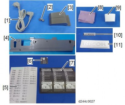
Check that you have the accessories indicated below.
No. | Descriptions | Q’ty | Remarks |
1 | Platen Cover | 1 | |
2 | Platen Sheet | 1 | |
3 | Feeler Guide | 1 | |
4 | Stepped Screw | 2 |
When installing this option, turn OFF the main power and unplug the power cord from the wall socket. If installing without turning OFF the main power, an electric shock or a malfunction may occur.
Install the stepped screws ![]() × 2).
× 2).

Install the feeler guide [A].
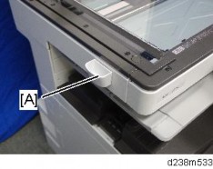
Install the platen cover [A].

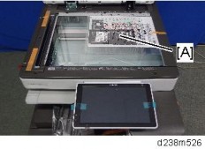
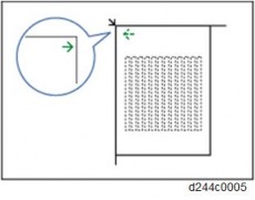
Place the platen sheet [A] on the exposure glass.
Line up the rear left corner of the platen sheet flush against corner [B] on the exposure glass.

Close the platen cover.
Open the platen cover.
Press the surface of the platen sheet gently to fix it on the platen cover securely.
No. | Description | Q’ty | Remarks |
1 | ARDF | 1 | |
2 | Screw | 2 | |
3 | Knob Screw | 2 | |
4 | Stud Screw (Small) | 1 | |
5 | Stud Screw (Large) | 1 | |
6 | Attention Decal – Top Cover | 1 |
Turn OFF the main power and unplug the power cord from the wall socket. If installing without turning OFF the main power, an electric shock or a malfunction may occur.
Do not turn the power on until you perform "adjustment after installation," or it may not start normally.
Remove all the tapes and shipping retainers.
Insert the two stud screws ([A] is the larger stud, [B] is the smaller stud).

Mount the ARDF [A] by aligning the screw keyholes [B] of the ARDF support plate over the stud screws.
Slide the ARDF toward the front of the machine.
Secure the ARDF with the two knob screws [C].

Align the rear left corner of the platen sheet [A] with the corner [B] on the exposure glass.
Close the ARDF.
Open the ARDF and check that the platen sheet is correctly attached.

Remove the rear cover [A].
Remove the small disposable cover [A] on the rear cover (on the right side).
Connect the ARDF cable as shown and mount the bracket [A] on the machine’s rear frame.
Make sure to connect the grounding wire.
Connect the scanner cable to the connector at the machine’s rear.
Reattach the rear cover.
Lift the ARDF original tray.
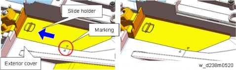
Slide the stamp holder [A] out and install the stamp cartridge in it, if necessary.
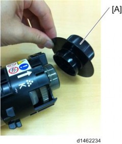
After the stamp installation, be sure to slide the holder in correctly. Make sure to slide it in thoroughly until the reference marks on the holder and exterior cover are aligned. If it is not mounted correctly, the machine detects a J001 paper jam.
Attach the decals [A] [B] to the top cover as shown. Choose the language that you want.

Plug in and turn ON the main power.
Set SP4-688-001 (DF Density Adjustment ARDF) to "106".
Check the ARDF operation, and make a full size copy. Check that the registrations (side-to-side and leading edge) and image skew are correct. If they are not, adjust the registrations and image skew (see page 4-217 "ARDF").
When feeding thin paper, adjust the sliding tray to the point shown below [A]. When feeding normal paper, adjust the sliding tray to the point shown below [B]. If not, it may cause problems as follows:
Original jam
Original curl
Originals cannot be stacked neatly
No. | Description | Q’ty | Remarks |
1 | Attention Decal – Top Cover | 1 | |
2 | Ferrite Core (L) | 1 | |
3 | Ferrite Core (S) | 1 | |
4 | Face-Up Document Decal | 1 | |
5 | Knob Screw | 2 | |
6 | Stud Screw | 2 | |
7 | Screw (3x6) | 4 |
Turn OFF the main power and unplug the power cord from the wall socket. If installing without turning OFF the main power, an electric shock or a malfunction may occur.
Do not turn the power on until you perform "adjustment after installation," or it may not start normally.
When unpacking, hold both sides of the SPDF and take it out of the box.

Place the unit on the machine temporarily, and remove the orange tapes and shipping retainers.

Remove the accessories in the package (boards, fixing screws, etc.).
Attach the 2 stepped screws to the machine.
Align the hinges of the SPDF with the stepped screws, and attach them by sliding them in.

Fix the SPDF to the machine (coin screws×2)
Release the lever [A], then open the pressure plate sheet [B], and gently remove the protective sheet [C].
Remove the filament tape, and shut the pressure plate sheet.

Remove the platen sheet [A], and set it on the exposure glass.
Align it with the left scale and rear scale of the printer.
Close the SPDF slowly, and attach the platen sheet and SPDF.

Remove the rear cover [A].

Remove the small disposable covers [A] on the rear cover.

Remove the controller box cover [A]. Red Circle: Remove, Blue Circle: Loosen

Connect the SPDF cable as shown and mount the brackets [A] [B] on the machine’s rear frame.
Make sure to connect the grounding wire.
Connect the scanner cable to the connector at the machine’s rear.
Attach the scanner cable [A] with the bracket on the upper frame of the controller box.

Connect the cable to the IPU (CN564).
Tuck in the excess length portion of the cable to the back of the machine.

Attach the supplied ferrite core (L) [A] and ferrite core (S) [B].
Attach [A] close to the connector.
Attach [B] in the area near the end of the tube.

Reattach the controller box cover and the rear cover.
Attach the decals [A] [B] to the SPDF.

Turn ON the main power.
Set SP4-688-002 (Scan Image Density Adjustment 1-pass DF) to "101".
Execute SP4-730-002 (FROM Main Factory Setting Execution ON/OFF).
Check the vertical registration for the SPDF.
Create an original as shown in the following picture. The large white arrow indicates the direction of feed.

Copy the original and make sure that the position of the line [A] is within 0±1mm
If not within the standard, adjust with the SP modes.
SP6-006-001 (ADF Adjustment Side-to-Side Regist: Front) SP6-006-002 (ADF Adjustment Side-to-Side Regist: Rear)
Check the horizontal registration for the SPDF.
Copy the original and make sure that the position of the line [B] that you wrote on the original (see above) is within 0±2mm.
If not within the standard, adjust with the SP modes.
SP6-006-010 (ADF Adjustment L-Edge Regist (1-Pass): Front) SP6-006-011 (ADF Adjustment L-Edge Regist (1-Pass): Rear)
Check the skew.
Make sure that the difference between both end positions of the line [A] that you wrote on the original (see above) is within 0±2mm.
If not within the standard, change the position of the fixing screw [A] to the long hole [B] at the right hinge.
SP descriptions
SP4-688-002 (Scan Image Density Adjustment: 1-pass DF)
Adjusts density difference between Book and ADF. This SP is only for the SPDF models.
SP4-730-002 (FROM Main Factory Setting Execution ON/OFF)
Copies the parameters written in FROM in the SPDF to the engine board in the MFP. This SP is only for the SPDF models.