Timing | Solutions | Side effect |
| Set SP1-135-001 (Inrush Control) to "1 (ON)". Set SP1-135-002 (Flicker Control) to "1 (ON)". |
|
If it has not been improved in the above, do the following procedures in addition;
SP1-121-001 (Switch:Rotation Start/Stop:Time:After Reload) to "0 sec". |
| |
| Set SP1-135-002 (Flicker Control) to "1 (ON)". |
|
Troubleshooting
Related SP to Fusing Offsets
SP Name | SP No. | Value |
Print Target Temp.:Plain1:FC:Center | SP1-105-001 | As initial values + 10 °C are the upper limits, change values to improve offsets. |
Print Target Temp.:Plain1:BW:Center | SP1-105-003 | |
Print Target Temp.:Plain2:FC:Center | SP1-105-005 |
SP Name | SP No. | Value |
Print Target Temp.:Plain2:BW:Center | SP1-105-007 | |
Print Target Temp.: Thin:FC:Center | SP1-105-009 | |
Print Target Temp.: Thin:BW:Center | SP1-105-011 | |
Print Target Temp.: M-thick:FC:Center | SP1-105-013 | |
Print Target Temp.: M-thick:BW:Center | SP1-105-015 |
Troubleshooting
RE V IS ION H IST ORY | ||
Page | Date | Added/ Updated/ New |
None | ||
Detailed Descriptions
Scanner
Items | MP C2003/C2503 /C2011 | MP C6004/C5504/C4504 /C3504/C3004 | MP C2004/C2504 |
Scanner type | - | Short focus scanner For distortion correction: After replacing the scanner carriage, the correction value specified on the supplied sheet in the SP code must be entered. For details, see page 4-37 "Scanner Carriage". | |
Scanner carriage storage upon shipping | None | The scanner carriage must be moved to the lock position to lock the carriage to the scanner frame before shipping. | |
Main scanning magnification adjustment | Not available | Magnification adjustment is available for the main scanning direction with SP4-871-003, -004. | |
Image Processing
Items | MP C2003/C2503 /C2011 | MP C6004/C5504/C4504 /C3504/C3004 | MP C2004/C2504 |
SIO | Available | Not available The functions of this old board are built into the IPU. | |
Copy data security function | Available by option | Available by default on the IPU | |
Process Control
Items | MP C2003/C2503 /C2011 | MP C6004/C5504/C4504 /C3504/C3004 | MP C2004/C2504 |
MUSIC | Executing rough adjustment -> fine adjustment only | Process upon execution of SP2-111-004 (Forced Line Position Adj.: mode d) and [Color Registration] in the User Tools have been changed. | |
Normal Operation: rough adjustment -> fine adjustment -> contact MUSIC (new process)
With Imageable Area Extension Unit: rough adjustment -> fine adjustment
Detailed Descriptions
Laser Exposure
Items | MP C2003/C2503 /C2011 | MP C6004/C5504/C4504 /C3504/C3004 | MP C2004/C2504 |
Laser unit | LD 1 beam | MPC4504/C5504/C6004: LD 4 beams MP C3004/C3504: LD 1 beam | LD 1 beam |
PCDU (Photo Conductor and Development Unit)
Items | MP C2003/C2503 /C2011 | MP C6004/C5504/C4504 /C3504/C3004 | MP C2004/C2504 |
MPC4504/C5504/C6004: | |||
The seals for all colors | |||
Removal of PCDU seal | The seals must be pulled out for all colors. | must be wound up. MP C3004/C3504: The seal for K must be wound up with a special | The seals must be pulled out for all colors. |
tool, and the seals for | |||
CMY must be pulled out | |||
PCU | DC charge roller (Contact type) Correction SP value must be input when PCU is replaced No lubricant bar Discharge lamp is in the main frame | AC charge roller (No contact type) Lubricant bar No discharge lamp | DC charge roller (Contact type) Correction SP value must be input when PCU is replaced No lubricant bar Discharge lamp is in the main frame |
Items | MP C2003/C2503 /C2011 | MP C6004/C5504/C4504 /C3504/C3004 | MP C2004/C2504 |
MPC4504/C5504/C6004: | |||
OD (One-way circulation | |||
of developer) system | |||
Development unit | Two mixing coils, two-way circulation | MP C3004/C3504: K: OD (One-way circulation of developer) | Two mixing coils, two-way circulation |
system | |||
CMY: Two mixing coils, | |||
one way circulation |
Waste Toner
Items | MP C2003/C2503 /C2011 | MP C6004/C5504/C4504 /C3504/C3004 | MP C2004/C2504 |
Waste toner cover | With latch | Without latch | |
Image Transfer and Paper Transfer
Items | MP C2003/C2503 /C2011 | MP C6004/C5504/C4504 /C3504/C3004 | MP C2004/C2504 |
TM/ID sensor shutter | Available | Not Available | |
Detailed Descriptions
Feed / Transport Part
Items | MP C2003/C2503 /C2011 | MP C6004/C5504/C4504 /C3504/C3004 | MP C2004/C2504 |
Bypass tray / Main machine jam code | - | The following codes are used to isolate the cause: | |
Main tray paper exit | - | ||
Tray draw-in mechanism | Not Available | Available | Not Available |
Paper feed sensor/ Paper exit full sensor | Not Available | Available | Not Available |
Paper thickness (Duplex) | 52 - 169 g/m2 | 52 - 256 g/m2 | 52 - 169 g/m2 |
Removing wrinkle in tray | Screwed with L-shaped sheet metal | Support component and decal are provided User installable | |
JAM048: Transport Sensor Lag Jam from Bypass Tray
JAM051: Transport Sensor Lag Jam from 1st Feed Tray
Improved stacking performance after feedout by adding resilience to the paper with the paper exit driven roller (drum shape).
To prevent paper jam when the paper is delivered from the machine’s paper exit to the internal exit peripherals, attach the paper support guide (supplied with the peripherals).
Replaced the paper exit driven roller to a flat type roller to prevent jamming when paper is fed to the internal exit peripherals.
Fusing
Items | MP C2003/C2503 /C2011 | MP C6004/C5504/C4504 /C3504/C3004 | MP C2004/C2504 |
Curl correction | Not Available | Equipped with a curl correction mechanism at the fusing exit. | |
Fusing shield plate | Available | MP C6004/C5504/C4504: Available MP C3004/C3504: Not Available | Not Available |
Fusing shield plate position sensor | 2 | MP C6004/C5504/C4504: 1 MP C3004/C3504: - | - |
Heat conduction plate | Not Available | Available | |
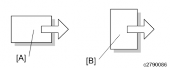
Others | - | Changed the drawer connector location | |
Changed the drawer connector location:
[A]: MP C6004/C5504/C4504/C3504/C2504/C2004 [B]: MP C2003/C2503/C2011

Detailed Descriptions
Electrical Parts
Items | MP C2003/C2503 /C2011 | MP C6004/C5504/C4504 /C3504/C3004 | MP C2004/C2504 |
SIO | Available | Not available The functions for this old board are included on the IPU | |
Human detection (Proximity sensor) | Not Available | Available Equipped with the proximity sensor (human detection sensor). | |
OPU | 1st generation Smart Operation Panel | 2nd generation Smart Operation Panel | |
Exterior Cover / Air Flows (Fan Control)
Items | MP C2003/C2503 /C2011 | MP C6004/C5504/C4504 /C3504/C3004 | MP C2004/C2504 |
Air flow | 8 fans | MP C6004/C5504/C4504: 10 fans MP C3004/C3504: 7 fans | 7 fans |
Duct | - | Increased the rigidity of the duct Changed the duct shape | |
Noise control | - | ||
Equipped with a Helmholtz silencer
Labyrinth structure of the exterior
Labyrinth structure of the exterior:
Exterior parts engage with each other to reduce the leaking of the driving noise.

Drive Parts
Items | MP C2003/C2503 /C2011 | MP C6004/C5504/C4504 /C3504/C3004 | MP C2004/C2504 |
Noise control | - | From the usual non-helical gears [A], we increased the use of helical gears [B] to increase the efficiency of engagement. This has also reduced the rattling noise due to the increased gear engagement. | |
Silencing grease for the drive parts | - | Grease is applied to over 100 parts, including gears, shafts, and bearings, to reduce the driving noise. | |
Detailed Descriptions
Others
Changing the Default Value for the Binding Margin
Until the last model, the default value for the binding margin was “5 mm on the right (on the back of the sheet)” when copying on both sides, in order to align the prints on both sides when punching. This has occasionally caused the paper edges to appear on the printed copies.
Thus, in this series, the default value for the binding margin is changed to “0 mm on the right (on the back of the sheet)” and the default value to mask the paper edge (SP mode) is also changed to reduce the chance of the black streak appearing.
Binding Margin Setting

Changed Default Values in the SP mode
SP4-012-001 (Set Scale Mask Book:Sub Ledge) 0 -> 1mm SP4-012-003 (Set Scale Mask Book:Main:Ledge) 0 -> 1mm
SP6-006-007 (ADF Adjustment Rear Edge Erase Front) 0 -> -2.3mm
SP6-006-014 (ADF Adjustment T-Edge Erase (1-Pass): Front) -1.5 -> -3.0mm SP6-006-015 (ADF Adjustment T-Edge Erase (1-Pass): Front) -1.5 -> -2.5mm

No. | Description | No. | Description |
1 | Operation panel | 6 | Auto paper size (APS) sensor |
2 | Anti-condensation heater (Scanner heater) *1 | 7 | Scanner lamp unit (LED) |
3 | Scanner HP sensor | 8 | Scanner motor |
4 | ARDF/Platen cover sensor | 9 | Sensor board unit (SBU) |
5 | Auto paper size (APS) sensor |
* Service part
Detailed Descriptions

No. | Description | No. | Description |
1 | Laser optics positioning motor (Y) | 5 | Polygon mirror motor |
2 | Synchronizing detector board: M/Y-S | 6 | LD drive board (M/Y) |
3 | Laser optics positioning motor (M) | 7 | LD drive board (Bk/C) |
4 | Laser optics positioning motor (C) | 8 | Synchronizing detector board: Bk/C-S |

No. | Description |
1 | Temperature and humidity sensor |
2 | Interlock switch: right door |
3 | ITB contact and release sensor |
4 | Paper transfer contact and release motor |
5 | TM/ID sensor (rear) |
6 | TM/ID sensor (center) |
7 | TM/ID sensor (front) |
Detailed Descriptions

No. | Description | No. | Description |
1 | PCDU (Y) | 3 | PCDU (C) |
2 | PCDU (M) | 4 | PCDU (Bk) |

No. | Description | No. | Description |
1 | ID chip contact board (Y) | 10 | Toner end sensor (Y) |
2 | Toner bottle drive motor (Y) | 11 | Toner supply motor (M) |
3 | ID chip contact board (M) | 12 | Toner end sensor (M) |
4 | Toner bottle drive motor (M) | 13 | Toner supply motor (C) |
5 | ID chip contact board (C) | 14 | Toner end sensor (C) |
6 | Toner bottle drive motor (C) | 15 | Toner end sensor (Bk) |
7 | ID chip contact board (Bk) | 16 | Toner supply motor (Bk) |
8 | Toner bottle drive motor (Bk) | 17 | Waste toner bottle full sensor |
9 | Toner supply motor (Y) | 18 | Waste toner bottle set sensor |
Detailed Descriptions

No. | Description | No. | Description |
1 | Tray set switch (1st feed tray) | 8 | Transport sensor (2nd Feed Tray) |
2 | Lift motor (1st feed tray) | 9 | Paper end sensor (2nd feed tray) |
3 | Tray set switch (2nd feed tray) | 10 | Upper limit sensor (2nd feed tray) |
4 | Lift motor (2nd feed tray) | 11 | Transport sensor (1st feed tray) |
5 | Registration sensor | 12 | Paper end sensor (1st feed tray) |
6 | Paper size switch (2nd Feed Tray) | 13 | Upper limit sensor (1st feed tray) |
7 | Anti-condensation heater |

No. | Description | No. | Description |
1 | Duplex entrance motor | 5 | Bypass pick-up solenoid |
2 | Right door open/close sensor | 6 | Bypass / Duplex motor |
3 | Duplex entrance sensor | 7 | Duplex exit sensor |
4 | Duplex guide plate open/close sensor | 8 | Bypass paper end sensor |
Detailed Descriptions

No. | Description |
1 | Bypass width sensor |
2 | Bypass length sensor |

No. | Description | No. | Description |
1 | Pressure roller HP sensor | 7 | Fusing sleeve thermostat (center) |
2 | Thermopile (edge) | 8 | Non-contact thermistor (center) |
3 | Thermopile (center) | 9 | Pressure roller thermistor (center) |
4 | Fusing exit sensor | 10 | Non-contact thermistor (edge) |
5 | Fusing lamp | 11 | Pressure roller thermistors (edge, full-bleed edge) |
6 | Fusing sleeve thermostat (edge) |
Detailed Descriptions

No. | Description | No. | Description |
1 | Reverse motor | 5 | Fusing entrance sensor |
2 | Reverse sensor | 6 | Fusing exit sensor |
3 | Paper exit sensor | 7 | Fusing exit drive solenoid (installed on the main machine) |
4 | PTR open/close sensor | 8 | Paper exit solenoid |

No. | Description | No. | Description |
1 | Paper exit cooling fan | 5 | Imaging temperature sensor (Thermistor) |
2 | Development intake fan | 6 | Toner supply cooling fan |
3 | PSU cooling fan | 7 | Fusing exhaust fan |
4 | Ozone exhaust fan |
Detailed Descriptions

No. | Description | No. | Description |
1 | Imaging IOB | 6 | Transport motor |
2 | Development motor: CMY | 7 | PCU motor: Black / ITB drive motor |
3 | PCU motor: CMY | 8 | Registration motor |
4 | Development Solenoid | 9 | Fusing motor |
5 | Paper feed motor | 10 | Paper exit / Pressure release motor |

No. | Description | No. | Description |
1 | Proximity sensor (Human detection sensor) | 8 | PSU (DC power) |
2 | Interlock switch: front cover | 9 | PSU (AC controller board) |
3 | HVP_TTS | 10 | BCU |
4 | Main power switch | 11 | Controller box cooling fan |
5 | Control board | 12 | IPU |
6 | HDD | 13 | Proximity sensor (Human detection sensor) board |
7 | Paper transport IOB |
Detailed Descriptions
The short focus scanner is realized by implementing a lens block (SBU, CCD, and Lens) on the carriage.
After the scanner lamp unit emits the light to the document, the light goes through route shown below and reaches the CCD.
Scanner lamp unit (LED) -> Original -> 1st mirror (13) -> 2nd mirror (3) -> 3rd mirror (6) -> 2nd mirror (3) -> 4th mirror (5) -> 5th mirror (14) -> lens -> pre-sensor lens -> CCD
No. | Description | No. | Description |
1 | Sheet-through exposure glass | 9 | Sensor board unit (SBU) |
2 | Exposure glass | 10 | CCD |
3 | 2nd mirror | 11 | Pre-sensor lens |
4 | Scanner lamp unit (LED) | 12 | Lens |
5 | 4th mirror | 13 | 1st mirror |
6 | 3rd mirror | 14 | 5th mirror |
7 | Scanner motor | 15 | Anti-condensation heater* (Scanner heater) |
8 | APS sensors |
*Service part
Reading System
Two scan modes are available: book mode (platen mode) and ADF mode (sheet-through method).
In book mode (platen mode), the scanner scans the document from left to right.
When the ADF is used (ADF mode), the scanner is fixed in the home position on the left side, and the document is transported and read (sheet-through method).
Scanner
Scanner lamp
The light source is an LED. The LED emits little heat (low power consumption), and has excellent light output rise characteristics.
CCD
The 3 line color CCD converts shade in the document to 3 color (B, G, and R) electrical signals. The use of a 4.7 µm image CCD achieves low-cost and compactness.
Reflection plate (reflector)
The reflection plate reflects light from the scanner lamp, and collects light for the document read unit. The light which illuminates the document is adjusted to be the same on the left and right so as not to cast any shadow on the document.
White reference seal
A white reference seal for shading correction is affixed to the underside of the scale on the left of the MFP. This is read by the scanner and CCD when the power is ON. The data read are temporarily stored in a RAM, and used for correction of document image data.
Detailed Descriptions
Scanner Drive
The scanner is driven by the scanner motor [D] via the timing belt [C]. For each mode, reading is completed in one pass.
Position control of the scanner carriage [B] is based on the scanner HP sensor [A].

Operation Flowchart
Overall Flowchart

Scanner Carriage Storage Control
To protect the scanner carriage, the carriage must be locked to the scanner frame before shipping. The scanner can be moved to the shipping lock position with SP4-806-001 (Scanner carriage storage operation).
If pre-shipping check is required, make sure to move the scanner carriage to the right position with SP4-806-001 and mount the locking parts.
SC121-00 will occur when the power is turned on or scanning takes place while the carriage is locked.
Document Size Detection
Detailed Descriptions
In this MFP, for document size detection, two reflecting sensors are used for the sub scanning direction, and a CCD is used for the main scanning direction.
Sub scanning direction
The document size is detected by ON/OFF of the sensor. The pressure plate open/close sensor is used for document size detection timing. When the pressure plate open/close sensor has changed from "no cover" to "cover," the size is detected.
Main scanning direction
RGB color densities at 3 locations (S1, S2, S3) are detected by a CCD, and when any of the RGB densities is 12 digits or more, it is determined that a document is present.
The pressure plate open/close sensor is used for document size detection timing. When the pressure plate open/close sensor detects "no cover," the scanner lamp is moved to the right; when it detects "cover," the scanner lamp is moved to home position while lit, and during this time, the size is read.

Document size | Sensor response | ||||||
Size | Direction | Dimensions (main × sub) | S1 | S2 | S3 | L1 | L2 |
A3 | SEF | 297x420 | - | - |
|
|
|
B4 | SEF | 257x364 | - |
| - |
|
|
A4 | SEF | 210x297 |
| - | - |
| - |
A4 | LEF | 297x210 | - | - |
| - | - |
B5 | SEF | 182x257 | - | - | - |
| - |
B5 | LEF | 257x182 |
| - | - | - | |
Document size | Sensor response | ||||||
A5 | SEF | 148x210 | - | - | - | - | - |
A5 | LEF | 210x148 |
| - | - | - | - |
B6 | SEF | 128×182 | - | - | - | - | - |
B6 | LEF | 182×128 | - | - | - | - | - |
DLT | SEF | 11"×17" | - | - |
| - |
|
10×15 | SEF | 10"×15" | - |
| - | - |
|
USB4 | SEF | 10"×14" | - |
| - | - |
|
LG | SEF | 8 1/2"×14" |
| - | - | - |
|
Oficio | SEF | 8 1/2"×13.4" |
| - | - | - |
|
Foolscap | SEF | 8 1/2"×13" |
| - | - | - |
|
Folio | SEF | 8 1/4"×13" |
| - | - | - |
|
F | SEF | 8"×13" |
| - | - | - |
|
LT | SEF | 8 1/2"×11" |
| - | - |
| - |
LT | LEF | 11"×8 1/2" | - | - |
| - | - |
8×10 | SEF | 8"×10" |
| - | - |
| - |
10×8 | LEF | 10"×8" | - |
| - | - | - |
Executive | SEF | 7 1/4"×10 1/2" | - | - | - |
| - |
HLT | SEF | 5 1/2"×8 1/2" | - | - | - | - | - |
HLT | LEF | 8 1/2"×5 1/2" |
| - | - | - | - |
8kai | SEF | 267×388 | - |
| - | - |
|
16kai | SEF | 194×267 | - | - | - |
| - |
16kai | LEF | 267×194 | - |
| - | - | - |
Detailed Descriptions
The document width (main scanning direction) is detected by the sensor indicated with ![]() ’.
’.
How to check the sensor state
SP4-301 (Operation Check APS Sensor)
How to read the screen (7)00000000(0)
0: no document
1: document present
When the sensor responds, bit 0 is displayed as "1."
SP4-310 (Scan Size Detect Value)
Viewed from the control panel, labeling positions from rear to front S1-S3 in that order, the RGB density at each position is displayed in digit units (the value just before scan is displayed).
Other
SP4-303 (Min Size for APS)
Sets the display when non-standard (small size) size original is detected. 0: Display message "Original size unknown".
1: Operate assuming the original size is A5 LEF (HLT LEF for inches).
SP4-305-001(8K/16K Detection)
By changing this SP, you can change between A4 size/letter size or Chinese paper size (8×16).
0: Normal setting. (Default)
1: When detecting A4/LT size -> Assume that it is A4 when SEF, LT when LEF. 2: When detecting A4/LT size -> Assume that it is LT when SEF, A4 when LEF. 3: Change to 8K/16K settings.
A3, B4 -> 8K LEF
A4 LEF, B4 LEF, A5 LEF -> 16K LEF A4 SEF, B4 SEF, A5 SEF -> 16K SEF
SP5-126 (Set F-size Document)
Selects the paper size for the F-size original.
0: When detecting Foolscap -> Assume that the size is 8 1/2"x13". (Default) 1: When detecting Folio -> Assume that the size is 8 1/4"x13".
2: When detecting F -> Assume that the size is 8"/13".
SP4-308 (Scan Size Detection)
Sets CCD original size detection and APS original size detection. 0: Disable: Not detect original size
1: Enable: Detect original size by the CCD unit
2: APS: APS sensor is used for detecting original size.
SP4-309-004 (Scan Size Detect:Setting LED PWM Duty)
If the user specifies that the pre-scan lamp is too bright, the brightness pre-scan can be reduced by decreasing the value of SP4-309-004 (Scan Size Detect:Setting LED PWM Duty). However, if the lamp brightness is reduced, size detection for a document with a large number of solid images will be less accurate.
SP5-135 (LG_Oficio Change)
1: When detecting LG size -> Assume that the size is 8 1/2"x14".
2: When detecting Oficio size -> Assume that the size is 8 1/2"x13.4". (Default)
Improved Tolerance to Black Lines When Paper Passes through ARDF/SPDF
The original document does not come in contact with the sheet-through exposure glass, which prevents adhesive dirt (ball pen ink) on the document from adhering to the sheet-through exposure glass.
ADF cross-section diagram, non-contact scanning

[A]: Sheet
[B]: Sheet-through exposure glass [C]: Read position
[D]: Document
Contact scanning
As the document comes in contact with the sheet-through exposure glass this is useful for dealing with adhesion of free dirt particles (paper scraps, etc.). (Self-cleaning mechanism using paper)
On the other hand, sticky dirt adhering to the document sticks to the sheet-through exposure glass, and may give rise to the appearance of black lines.
ADF cross-section diagram, contact scanning

Detailed Descriptions
[A]: Sheet-through exposure glass [B]: Read position
[C]: Document
If black lines due to free dirt particles appear within a short time, such as when users have documents with large amounts of paper scraps, you can change from the non-contact scanning system to the contact scanning system with the procedure in Troubleshooting - Vertical Streaks on Copies due to Scanning Problems.
Reference (reading position correction)
By changing SP4-020-001 (Dust Check Dust Detect:On/Off), when dirt is detected at the reading position, the reading position may be changed to avoid the dirt.
(If it cannot be avoided, an alert is displayed on the control panel advising the user to perform target glass cleaning).
Image diagram

[A]: Read position
[B]: Sheet-through exposure glass [C]: Dirt
Dirt is detected when a document passes through, so the alert will not disappear until reading of the next document begins, even after the sheet-through exposure glass cleaning is performed.
If dirt is detected not on the sheet-through exposure glass but on the background guide plate, the alert will not disappear even if the glass is wiped.
The time required for the first copy is slightly (almost imperceptibly) longer.
The detection threshold value can be changed using SP4-020-002 (Dust Check Dust Detect:Lvl). (The larger the value is, the smaller the dirt particles that can be detected become.)
It is prohibited to change the setting of SP4-020-003 (Dust Check Lvl Dust Reject:Lvl).
Difference between Non-contact Transport and Contact Transport in DF Scanning
Transport Method | Non-contact Transport | Contact Transport |
Descriptions |
Because of the film attached to the glass, the original doesn’t contact the glass. |
While passing, the original contacts the glass. |
Merit | It almost never causes stripes on the image that arise from foreign substances transferring from the original to the glass. | It almost never causes stripes on the image that arise from dust on the glass, because the glass is cleaned by contact with the transported original. |
Demerit | Compared with the contact method, stripes on the image caused by dust occur more often. | Compared with the non-contact method, stripes on the image caused by foreign substances transferred from the surface of an original to the glass occur more often. |
Transport Method | Non-contact Transport | Contact Transport |
Aim | To improve prevention of stripes in the image caused by sticky foreign substances. | Considering the target users of this machine, it’s important to improve prevention of stripes caused by dust in the path |
Note | sheet-through glass with the film attached on the glass. non-contact, or vice versa) by replacing some parts.*1 | - |
Be sure to replace the
When you attach the film on the glass, you need to keep the left scale attached on the glass in order to fix the location of the film.*1
You can change the method (contact method to
Detailed Descriptions
*1: For details, page 6-309 "Vertical Streaks on Copies due to Scanning Problems".
Anti-Condensation Heater
A
Under low temperature conditions, condensation may appear on optical parts (such as mirrors). This will cause image deletion, blacked out images, and gray images. As a countermeasure, there is an anti-condensation heater [A] that is an optional service part. This heater turns on automatically when the power source turns off.
Anti-condensation heater
Detailed Descriptions
SBU
Functions
Performs Black level correction and White level correction, Creating the SBU test pattern, and A/D conversion.
This machine is equipped with a short focus scanner and the SBU is located on the scanner carriage.
Operation overview
Samples 2 analog signals (ODD, EVEN) from RGB output from the 3-line CCD, and converts them to digital signals by an A/D converter. The digital signals are output to the IPU.
SP correction value storage
The SBU correction value is stored in an EEPROM on the BCU.
Execute the following SP settings when the scanner carriage is replaced. (Lens block is located on the scanner carriage.)
SP4-871-002 (Distortion Correction Distortion Initialization)
SP4-880-001 (Dot shift amount between R Line and G Line).
SP4-880-002 (Dot shift amount between G Line and B Line).
SBU Test Mode
There is an SP code to create a test pattern which can be used as a diagnostic tool to troubleshoot problems in the SBU:
SP4-699-001 (SBU Test Pattern Change) Pattern 1: fixed value
Pattern 2: main scanning gradation pattern Pattern 3: width scanning gradation pattern
Pattern 4: main scanning/width scanning lattice pattern SBU has a function to generate four test patterns.
IPU
Image processing function overview
The image signals from the SBU are subjected to various image processing, and output to the controller (memory). The image signals from the controller (memory) are received, and output to the LDB (the LDB is provided in the write unit).
Image processing overview (copy application)
Digital signal data output from the SBU is subjected to shading correction and line interval correction, as well as image processing, which are performed by the IPU. Finally, the data is sent to the machine as digital signals-4 bit/pixels.
Image processing items | Details |
Shading correction | Corrects for uneven scanner lamp lighting, and scatter in CCD light receiving sensitivity. |
Line interval correction | Line shift during subscanning magnification/reduction by scanner. Corrects integer part. |
Dot correction | Line shift during subscanning magnification/reduction by scanner. Corrects below decimal point. |
Vertical line correction | Corrects a vertical striped image during sheet-through ADF. |
Image area separation | Determines text parts and photo parts of image. |
Scanner gamma correction | Corrects scatter of image data relative to exposure amount. From reflectivity linear to density linear. |
Filter | Performs image sharpness adjustment and removes moire. |
ADS | Performs natural complexion removal in full color mode. |
Color compensation preprocessing | Determines hue in masking mode, and improves chromaticity. |
Color compensation | Converts RGB data to density value CMYK data of color materials. |
Image magnification change | Arbitrarily changes main scanning magnification, subscanning fixed image reduction and magnification of scanner image. |
Image processing items | Details |
Image shift function | Shifts image data in the main scanning or subscanning directions. |
Image binarization function | In scanner mode, outputs a binary signal. |
Image mask | Masks an area outside a frame of an arbitrary region in scanner or printer data. |
Image compression/expansion | Compresses or expands an image. |
Printer gamma correction | Adjusts exposure amount of photosensitive body relative to image density. |
Gradation processing | Applies 600dpi, 4bit 16 value gradation processing. |
Detailed Descriptions
Four stations (one for each color).
No. | Description | No. | Description |
1 | 2nd mirror | 8 | F-theta lens-M/Y |
2 | Laser optics positioning motor (C) | 9 | LD drive board |
3 | Laser optics positioning motor (M) | 10 | Polygon mirror motor |
4 | 2nd mirror | 11 | LD drive board |
5 | Laser optics positioning motor (Y) | 12 | Cylinder lens |
6 | Cylinder lens | 13 | F-theta lens-Bk/C |
7 | 1st mirror | 14 | 2nd mirror |
Detailed Descriptions
Parts Construction
The write unit comprises a housing and the following main parts:

No. | Description | No. | Description |
1 | 1st mirror | 5 | F-theta lens |
2 | Dust shield glass | 6 | Soundproof glass |
3 | PCU (Y,M, C, K) | 7 | Polygon mirror motor |
4 | 2nd mirror |

No. | Description | No. | Description |
1 | LD drive board (M/Y) | 4 | Synchronizing detector board: Bk/C-S |
2 | LD drive board (Bk/C) | 5 | Synchronizing detector board: M/Y-S |
3 | Cylinder lens (Bk/C) | 6 | Cylinder lens (M/Y) |
Detailed Descriptions
LD Drive Board
The LD Unit is provided with two LD drive board. The beam system is a 1 beam type. The LD drive board comprises an LD (laser diode), PD (photodiode) and LD control unit.
The LD outputs the laser light to the PCU.
The PD continuously detects laser light from LD, and outputs it to the LD control unit.
The LD control unit adjusts the light amount of the LD based on the output signal of the PD. LD control board adjustment is not required in the field.
LD Safety Switch
To prevent the laser beam from turning on when the front cover or right door is open, the 5V supply to the LD drive board is interrupted when the interlock switch is open.
Circuit Diagram

Line Scanning Mechanism

[A]: Dust shield glass [B]: 1st mirror
[C]: F-theta lens
[D]: Polygon mirror motor
Mirror, lens
Laser diodes of each color emit light to match the paper transport timing. After passing through the cylinder lens (laser beam width correction), polygon mirror motor (main scanning line scan), F-theta lens (dot position correction and optical face tangle error correction), it reaches the drums of each color.
The F-theta lens has a two-stage integrated construction, and 2 color beam correction is performed with one lens.
Polygon mirror motor
The polygon mirror motor comprises two (upper and lower) 6-faced mirrors formed in an integral construction (these are combined in one unit).
In this MFP, 4 color simultaneous write is performed by the LD irradiating a polygon mirror.
* The rotation speed of the polygon mirror motor is controlled by LD/ Polygon mirror motor.
Synchronization sensor
There are two synchronization sensors, i.e., one on the K-C side, and one on the M-Y side. Each sensor detects light from one color, and synchronization for two colors is calculated from this.
There is only one sensor for each color. The sensor at the leading edge of the main scan line has been removed.
Scan line inclination and automatic adjustment mechanism
The laser optics positioning motor installed on the 2nd mirror adjusts the scan line inclination. This is done during automatic image position correction.
Detailed Descriptions
Sensor Construction
The ID Sensors (also called the TM/ID sensors) are used to measure the amount of toner on the transfer belt and to correct any errors in color registration.
The TD sensor (also called the ![]() sensor) is used to measure the toner density in the developer.
sensor) is used to measure the toner density in the developer.
Outline of the ID Sensors
The ID sensors are fixed onto the main frame, against the surface of the transfer belt. Color registration is checked by all three sensors; the front [A], center [B], and rear [C].
The center sensor [B] acts as an ID sensor and a MUSIC sensor.

Outline of the TD sensor
In this model, a non-contact toner density (TD) sensor, which we also call a mu ![]() ) sensor, is used for toner density control.
) sensor, is used for toner density control.
The TD sensor is attached on the lower side of the development unit. Unlike a HST sensor, the board of the TD sensor is exposed. So there is a cover around the sensor to protect it and to maintain a good contact between the sensor and development unit.
The TD sensor measures the permeability of the developer without contacting it, from the outside of the case, and converts the measured value to the toner density.
According to the toner density measured by this sensor, the proper amount of toner is supplied to the developer.
A counter corresponding to the frequency is used as the unit of TD sensor output. Thus, unlike a HST sensor which directly detects Vt, the TD sensor output is converted into Vt for toner supply control.
In the TD sensor, there is an ID chip storing the machine identification information, the running distance information of development unit and PCU, and other information used by image density control.
Outline
Process control adjusts the condition of the imaging hardware to maintain a constant image density. Process control is executed at the following times.
Process Control | Operative Condition | Related SPs | |
1 | PowerON ProCon :Set | When a certain time has passed after the previous job end (Except when recovering from an SC or jam) | SP3-530-001 SP3-530-002 SP3-530-003 SP3-530-004 SP3-530-005 SP3-530-006 SP3-530-007 SP3-530-008 |
2 | JobEnd ProCon :Set | When the value of the job end counter becomes more than the threshold (At job end) | SP3-534-001 to 004 SP3-534-011 to 014 |
Process Control | Operative Condition | Related SPs | |
3 | Interrupt ProCon :Set | When the value of the job interrupt counter becomes more than the threshold | SP3-533-001 to 004 SP3-533-011 to 014 |
4 | Non-useTime Procon :Set | When the value of the non-use time counter becomes more than the threshold | SP3-531-001 to 004 |
5 | Manual ProCon :Exe | When SP 3-011 is used | SP3-011-001 to 005 |
6 | Toner End Recovery | After the Toner End Status is cleared (Recovery is NOT done in the near end status) | - |
7 | Initial Developer Setting Process Control | When the machine detects a new PCU or development unit | - |
Detailed Descriptions
Result Code for Executing Process Control
Check the following SPs.
SP3-012-001 to 010 (Front)
SP3-012-011 to 020 (Center)
SP3-012-021 to 030 (Rear)
Category | Code | Result name | Description |
00 and larger | 00 | Not executed | Factory default setting (SP default) |
10 and larger Result (Normal) | 11 | Succeeded | - |
40 and larger ID Sensor | 41 | ID sensor output error (Max) | Vt > Max |
42 | ID sensor output error (Min) | Vt < Min |
Category | Code | Result name | Description |
43 | ID Sensor error (Max) | Development gamma is in target, but Vt value is less than upper limit. | |
44 | ID Sensor error (Min) | Development gamma is in target, but Vt value is less than lower limit. | |
45 and larger ID Pattern detection | 45 | ID Pattern extract error | Cannot detect ID Pattern |
50 | Vmin_Bk/K2 error (Max) | K:Vmin_Bk / CMY:K2 > Max | |
51 | Vmin_Bk/K2 error (Min) | K:Vmin_Bk / CMY:K2 < Min | |
52 | K5 error (Max) | K5 > Max | |
53 | K5 error (Min) | K5 < Min | |
54 | K5 calculated approximate point error | K5 calculated approximate point < Min | |
55 | Development gamma error (Max) | Development gamma > Max | |
56 | Development gamma error (Min) | Development gamma < Min | |
57 | Start developing voltage: Vk error(Max) | Start developing voltage: Vk > Max | |
58 | Start developing voltage: Vk error(Min) | Start developing voltage: Vk < Min | |
59 | Not enough valid data | Adhesion amount data for development gamma calculation point is under 2. | |
90 and larger Result(End) | 90 | Potential not adjusted | Potential control method is set as [0:FIX]. |
99 | Stopped | Stopped by door open, power off, error. (Set when execute.) |