Cause verification | Problem Judgement |
Turn the referenced motor OFF with OUTPUT check | Drive sound heard |
Turn the referenced motor ON with OUTPUT check | Drive sound not heard |
Troubleshooting
Reconnect the connector.
Replace the motor.
Replace the Paper Transport IOB.
Replace the harness.
Cause verification | Problem Judgement |
Turn the referenced motor OFF with OUTPUT check | Drive sound heard |
Turn the referenced motor ON with OUTPUT check | Drive sound not heard |
Reconnect the connector.
Replace the motor.
Replace the Paper Transport IOB.
Replace the harness.
Cause verification | Problem Judgement |
Turn the referenced motor OFF with OUTPUT check | Drive sound heard |
Turn the referenced motor ON with OUTPUT check | Drive sound not heard |
Reconnect the connector.
Replace the motor.
Replace the Paper Transport IOB.
Replace the harness.
Cause verification | Problem Judgement |
Execute an INPUT check when there is no paper at the position of the referenced sensor. | 1: Paper detected |
Execute an INPUT check when there is paper at the position of the referenced sensor. | 0: Paper not detected |
Clean the sensor.
Reconnect the connector.
Replace the sensor.
Replace the Paper Transport IOB.
Replace the harness.
Check the paper position (Check whether or not the leading edge of the paper, side paper guide, and end paper guide are positioned according to the manual.) | |
Check if the paper has reached the maximum stackable limit of the side paper guide. | Reduce the paper to below the stackable limit. |
Check if extra thin paper or thick paper exceeding the supported paper thickness is being used. | Use a supported paper type. |
Check if the paper thickness and size are detected correctly. | Set the paper thickness and size to the correct value. |
Check if the paper being used produces a lot of paper dust. | Change the paper type (if possible). |
Check if there is no double feeding. | Fan the paper. |
Check if the paper feed tray is not stained with a lot of paper dust. | Clean the paper feed tray. |
Check if the paper roller is not stained with paper dust. | Clean the pick-up roller, feed roller, and friction roller for 1st feed tray. |
Check the paper orientation.
Turn the paper in the feed tray upside down.
Troubleshooting
Cause verification | Problem Judgement |
Execute an INPUT check when there is no paper at the position of the referenced sensor. | 0 :Paper detected |
Execute an INPUT check when there is paper at the position of the referenced sensor. | 1: Paper not detected |
Clean the sensor.
Reconnect the connector.
Replace the sensor.
Replace the Paper Transport IOB.
Replace the harness.
Cause Verification | Problem Judgement |
Turn the referenced motor OFF with OUTPUT check | Drive sound heard |
Turn the referenced motor ON with OUTPUT check | Drive sound not heard |
Clean the sensor.
Reconnect the connector.
Replace the sensor.
Replace the Paper Transport IOB.
Replace the harness.
Cause verification | Problem Judgement |
Turn the referenced motor OFF with OUTPUT check | Drive sound heard |
Turn the referenced motor ON with OUTPUT check | Drive sound not heard |
Reconnect the connector.
Replace the motor.
Replace the Paper Transport IOB.
Replace the harness.
Check the paper position (Check whether or not the leading edge of the paper, side paper guide, and end paper guide are positioned according to the manual.) | |
Check if the paper has reached the maximum stackable limit of the side paper guide. | Reduce the paper to below the stackable limit. |
Check if extra thin paper or thick paper exceeding the supported paper thickness is being used. | Use a supported paper type. |
Check if the paper thickness and size are detected correctly. | Set the paper thickness and size to the correct value. |
Check if the paper being used produces a lot of paper dust. | Change the paper type (if possible). |
Check if there is no double feeding. | Fan the paper. |
Check if the paper feed tray is not stained with a lot of paper dust. | Clean the paper feed tray. |
Check if the paper roller is not stained with paper dust. | Clean the pick-up roller, feed roller, and friction roller for 2nd feed tray. |
Check the paper orientation.
Turn the paper in the feed tray upside down.
Troubleshooting
Cause verification | Problem Judgement |
Execute an INPUT check when there is no paper at the position of the referenced sensor. | 0 :Paper detected |
Execute an INPUT check when there is paper at the position of the referenced sensor. | 1: Paper not detected |
Clean the sensor.
Reconnect the connector.
Replace the sensor.
Replace the Paper Transport IOB.
Replace the harness.
Cause verification | Problem Judgement |
Turn the referenced motor OFF with OUTPUT check | Drive sound heard |
Turn the referenced motor ON with OUTPUT check | Drive sound not heard |
Reconnect the connector.
Replace the motor.
Replace the Paper Transport IOB.
Replace the harness.
Cause verification | Problem Judgement |
Turn the referenced motor OFF with OUTPUT check | Drive sound heard |
Turn the referenced motor ON with OUTPUT check | Drive sound not heard |
Reconnect the connector.
Replace the motor.
Replace the Paper Transport IOB.
Replace the harness.
Check if there is no double feeding. | Fan the paper. |
Cause verification | Problem Judgement |
Execute an INPUT check when there is no paper at the position of the referenced sensor. | 0 :Paper detected |
Execute an INPUT check when there is paper at the position of the referenced sensor. | 1: Paper not detected |
Clean the sensor.
Reconnect the connector.
Replace the sensor.
Replace the Paper Transport IOB.
Replace the harness.
Check if the leading edge of the paper and the paper feed guide are wet. | If condensation has occurred inside the machine, leave the machine idle for a few minutes to remove condensation. |
Check if there is no double feeding. | Fan the paper. |
Check if the paper is curled too much. | If the paper is curled too much, switch on the anti-condensation heater for paper tray. |
Check if extra thin paper or thick paper exceeding the supported paper thickness is being used. | Use a supported paper type. |
Check if the paper thickness and size are detected correctly. | Set the paper thickness and size to the correct value. |
Troubleshooting
Cause verification | Problem Judgement |
Execute an INPUT check when there is no paper at the position of the referenced sensor. | 0 :Paper detected |
Execute an INPUT check when there is paper at the position of the referenced sensor. | 1: Paper not detected |
Clean the sensor.
Reconnect the connector.
Replace the sensor.
Replace the Paper Transport IOB.
Replace the harness.
Cause verification | Problem Judgement |
Turn the referenced motor OFF with OUTPUT check | Drive sound heard |
Turn the referenced motor ON with OUTPUT check | Drive sound not heard |
Reconnect the connector.
Replace the motor.
Replace the Paper Transport IOB.
Replace the harness.
Cause verification | Problem Judgement |
Turn the referenced solenoid OFF with OUTPUT check | Drive sound heard |
Turn the referenced solenoid ON with OUTPUT check | Drive sound not heard |
Reconnect the connector.
Replace the solenoid.
Replace the Paper Transport IOB.
Replace the harness.
Check if the leading edge of the paper and the paper feed guide are wet. | If condensation has occurred inside the machine, leave the machine idle for a few minutes to remove condensation. |
Check if there is no double feeding. | Fan the paper. |
Check if the paper is curled too much. | If the paper is curled too much, switch on the anti-condensation heater for paper tray. |
Check if extra thin paper or thick paper exceeding the supported paper thickness is being used. | Use a supported paper type. |
Check if the paper thickness and size are detected correctly. | Set the paper thickness and size to the correct value. |
Troubleshooting
Cause verification | Problem Judgement |
Execute an INPUT check when there is no paper at the position of the referenced sensor. | 0 :Paper detected |
Execute an INPUT check when there is paper at the position of the referenced sensor. | 1: Paper not detected |
Clean the sensor.
Reconnect the connector.
Replace the sensor.
Replace the Paper Transport IOB.
Replace the harness.
Cause verification | Problem Judgement |
Turn the referenced motor OFF with OUTPUT check | Drive sound heard |
Turn the referenced motor ON with OUTPUT check | Drive sound not heard |
Clean the sensor.
Reconnect the connector.
Replace the sensor.
Replace the Paper Transport IOB.
Replace the harness.
Check if the leading edge of the paper and the paper feed guide are wet. | If condensation has occurred inside the machine, leave the machine idle for a few minutes to remove condensation. |
Check if there is no double feeding. | Fan the paper. |
Check if the paper is curled too much. | If the paper is curled too much, switch on the anti-condensation heater for paper tray. |
Check if extra thin paper or thick paper exceeding the supported paper thickness is being used. | Use a supported paper type. |
Check if the paper thickness and size are detected correctly. | Set the paper thickness and size to the correct value. |
Cause verification | Problem Judgement |
Execute an INPUT check when there is no paper at the position of the referenced sensor. | 0 :Paper detected |
Execute an INPUT check when there is paper at the position of the referenced sensor. | 1: Paper not detected |
Clean the sensor.
Reconnect the connector.
Replace the sensor.
Replace the Paper Transport IOB.
Replace the harness.
Cause verification | Problem Judgement |
Turn the referenced motor OFF with OUTPUT check | Drive sound heard |
Turn the referenced motor ON with OUTPUT check | Drive sound not heard |
Troubleshooting
Reconnect the connector.
Replace the motor.
Replace the Paper Transport IOB.
Replace the harness.
Check if there is no double feeding. | Fan the paper. |
Check if the paper is curled too much. | If the paper is curled too much, switch on the anti-condensation heater for paper tray. |
Check if extra thin paper or thick paper exceeding the supported paper thickness is being used. | Use a supported paper type. |
Check if the paper thickness and size are detected correctly. | Set the paper thickness and size to the correct value. |
Cause verification | Problem Judgement |
Execute an INPUT check when there is no paper at the position of the referenced sensor. | 0 :Paper detected |
Execute an INPUT check when there is paper at the position of the referenced sensor. | 1: Paper not detected |
Clean the sensor.
Reconnect the connector.
Replace the sensor.
Replace the Paper Transport IOB.
Replace the harness.
Cause verification | Problem Judgement |
Turn the referenced motor OFF with OUTPUT check | Drive sound heard |
Turn the referenced motor ON with OUTPUT check | Drive sound not heard |
Troubleshooting
Clean the sensor.
Reconnect the connector.
Replace the sensor.
Replace the Paper Transport IOB.
Replace the harness.
Cause verification | Problem Judgement |
Turn the referenced solenoid OFF with OUTPUT check | Drive sound heard |
Turn the referenced solenoid ON with OUTPUT check | Drive sound not heard |
Reconnect the connector.
Replace the solenoid.
Replace the Paper Transport IOB.
Replace the harness.
Check if there is no double feeding. | Fan the paper. |
Check if the paper is curled too much. | If the paper is curled too much, switch on the anti-condensation heater for paper tray. |
Check if extra thin paper or thick paper exceeding the supported paper thickness is being used. | Use a supported paper type. |
Check if the paper thickness and size are detected correctly. | Set the paper thickness and size to the correct value. |
Cause verification | Problem Judgement |
Execute an INPUT check when there is no paper at the position of the referenced sensor. | 0 :Paper detected |
Execute an INPUT check when there is paper at the position of the referenced sensor. | 1: Paper not detected |
Clean the sensor.
Reconnect the connector.
Replace the sensor.
Replace the Paper Transport IOB.
Replace the harness.
Cause verification | Problem Judgement |
Turn the referenced motor OFF with OUTPUT check | Drive sound heard |
Turn the referenced motor ON with OUTPUT check | Drive sound not heard |
Reconnect the connector.
Replace the sensor.
Replace the Paper Transport IOB.
Replace the harness.
Cause verification | Problem Judgement |
Turn the referenced motor OFF with OUTPUT check | Drive sound heard |
Turn the referenced motor ON with OUTPUT check | Drive sound not heard |
Troubleshooting
Reconnect the connector.
Replace the sensor.
Replace the Paper Transport IOB.
Replace the harness.
Check if there is no double feeding. | Fan the paper. |
Check if the paper is curled too much. | If the paper is curled too much, switch on the anti-condensation heater for paper tray. |
Check if extra thin paper or thick paper exceeding the supported paper thickness is being used. | Use a supported paper type. |
Check if the paper thickness and size are detected correctly. | Set the paper thickness and size to the correct value. |
Cause verification | Problem Judgement |
Execute an INPUT check when there is no paper at the position of the referenced sensor. | 0 :Paper detected |
Execute an INPUT check when there is paper at the position of the referenced sensor. | 1: Paper not detected |
Clean the sensor.
Reconnect the connector.
Replace the sensor.
Replace the Paper Transport IOB.
Replace the harness.
Check if there is no double feeding. | Fan the paper. |
Check if the paper is curled too much. | If the paper is curled too much, switch on the anti-condensation heater for the paper tray. |
Check if extra thin paper or thick paper exceeding the supported paper thickness is being used. | Use a supported paper type. |
Check if the paper thickness and size are detected correctly. | Set the paper thickness and size to the correct value. |
Troubleshooting
Cause verification | Problem Judgement |
Execute an INPUT check when there is no paper at the position of the referenced sensor. | 0 :Paper detected |
Execute an INPUT check when there is paper at the position of the referenced sensor. | 1: Paper not detected |
Clean the sensor.
Reconnect the connector.
Replace the sensor.
Replace the Paper Transport IOB.
Replace the harness.
Cause verification | Problem Judgement |
Turn the referenced motor OFF with OUTPUT check | Drive sound heard |
Turn the referenced motor ON with OUTPUT check | Drive sound not heard |
Reconnect the connector.
Replace the motor.
Replace the Paper Transport IOB.
Replace the harness.
Cause verification | Problem Judgement |
Execute an INPUT check when there is no paper at the position of the referenced sensor. | 1: Paper detected |
Execute an INPUT check when there is paper at the position of the referenced sensor. | 0: Paper not detected |
Reconnect the connector.
Replace the sensor.
Replace the Paper Transport IOB.
Replace the harness.
Cause verification | Problem Judgement |
Check if the feeler for 1st paper end sensor is unfastened. | Feeler is unfastened. |
Reinstall the feeler.
Check if there are any defects in the 1st paper feed unit.
Cause verification | Problem Judgement |
Execute an INPUT check when there is no paper at the position of the referenced sensor. | 1: Paper detected |
Cause verification | Problem Judgement |
Execute an INPUT check when there is paper at the position of the referenced sensor. | 0: Paper not detected |
Troubleshooting
Reconnect the connector.
Replace the sensor.
Replace the Paper Transport IOB.
Replace the harness.
Cause verification | Problem Judgement |
Check if the feeler for 2nd paper end sensor is unfastened. | Feeler is unfastened. |
Reinstall the feeler.
Check if there are any defects in the 2nd paper feed unit.
Cause verification | Problem Judgement |
Manually press the referenced switch (Done after detaching paper feeding tray 1 from the machine.) | 1: Not set |
Pull out paper feed tray 1 from the machine. | 0: Set |
Reconnect the connector.
Replace the sensor.
Replace the Paper Transport IOB.
Replace the harness.
Replace the 1st paper feed tray. | Replace the 1st paper feed tray. |
Cause verification | Problem Judgement |
Manually press the referenced switch (Done after detaching paper feeding tray 2 from the machine.) | 1: Not set |
Pull out paper feed tray 2 from the machine. | 0: Set |
Reconnect the connector.
Replace the sensor.
Replace the Paper Transport IOB.
Replace the harness.
Check the 2nd tray set sensor to see if there are any defects. | Replace the 2nd paper feed tray. |
Cause verification | Problem Judgement |
Press the 1st switch from the right on the size switch of paper feed tray 2 when seen from the front of the machine (Done after detaching paper feed tray 2) | Parameter other than 00000111 |
Press the 2nd switch from the right on the size switch of paper feed tray 2 when seen from the front of the machine (Done after detaching paper feed tray 2) | Parameter other than 00001011 |
Press the 3rd switch from the right on the size switch of paper feed tray 2 when seen from the front of the machine (Done after detaching paper feed tray 2) | Parameter other than 00001101 |
Cause verification | Problem Judgement |
Press the 4th switch from the right on the size switch of paper feed tray 2 when seen from the front of the machine (Done after detaching paper feed tray 2) | Parameter other than 00001110 |
Pull out paper feed tray 2 from the machine. | Parameter other than 00001111 |
Troubleshooting
Reconnect the connector.
Replace the sensor.
Replace the Paper Transport IOB.
Replace the harness.
Replace the switch for the pick-up arm.
Check the 2nd tray set sensor to see if there are any defects.
Cause verification | Problem Judgement |
Manually press the referenced switch (Done after opening the right door) | 1: Open |
Open the right door | 0: Close |
Reconnect the connector.
Replace the sensor.
Replace the Paper Transport IOB.
Replace the harness.
Cause verification | Problem Judgement |
Manually press the referenced switch (Done after opening the duplex guide plate) | 1: Open |
Open the duplex guide plate. | 0: Close |
Reconnect the connector.
Replace the sensor.
Replace the Paper Transport IOB.
Replace the harness.
Replace the 2nd paper feed tray.
Check the switch for the pick-up arm to see if there are any defects.
If the error occurs periodically, do the following steps. If the result is as shown in the "Problem Judgement" column, follow the solutions.
Cause verification | Problem Judgement |
Execute an INPUT check with no feeler in the sensor detection range (Done after detaching the waste toner bottle) | 1: Full |
Clean the sensor.
Reconnect the connector.
Replace the sensor.
Replace the Imaging IOB.
Replace the harness.
Troubleshooting
Cause verification | Problem Judgement |
Execute an INPUT check with feeler within the sensor detection range (Done after removing the waste toner bottle) | 0: Not full |
Clean the sensor.
Reconnect the connector.
Replace the sensor.
Replace the Imaging IOB.
Replace the harness.
Cause verification | Problem Judgement |
Execute an INPUT check with the feeler within the sensor detection range (Done after removing the waste toner bottle) | 1: Not set |
Reconnect the connector.
Replace the sensor.
Replace the Imaging IOB.
Replace the harness.
Cause verification | Problem Judgement |
Detach the waste toner bottle from the machine. | 0: Set |
Reconnect the connector.
Replace the sensor.
Replace the Imaging IOB.
Replace the harness.
Cause verification | Problem Judgement |
Execute an INPUT check with an object (e.g. paper) placed within the sensor detection range. | 1: Close |
Execute an INPUT check without an object (e.g. paper) placed within the sensor detection range. | 0: Open |
Clean the sensor.
Reconnect the connector.
Replace the sensor.
Replace the Paper Transport IOB.
Replace the harness.
Cause verification | Problem Judgement |
Turn ON the paper transfer unit open/close LED with OUTPUT check | 1: Close |
Execute an OUTPUT check without an object (e.g. paper) placed within the sensor detection range. | 0: Open |
Clean the LED.
Reconnect the connector.
Troubleshooting
Replace the LED.
Replace the Paper Transport IOB.
Replace the harness.
Cause verification | Problem Judgement |
Execute an INPUT check with an object (e.g. paper) placed within the sensor detection range | 1: Close |
Execute an INPUT check without an object (e.g. paper) placed within the sensor detection range | 0: Open |
Clean the sensor.
Reconnect the connector.
Replace the sensor.
Replace the Paper Transport IOB.
Replace the harness.
Cause verification | Problem Judgement |
Turn OFF the paper transfer unit open/close LED with OUTPUT check | LED lit |
Clean the LED.
Reconnect the connector.
Replace the LED.
Replace the Paper Transport IOB.
Replace the harness.
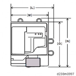
Side-to-side registration can be adjusted by the docking bracket for SR3220 [A] (and the docking bracket screw [B]).

[A]: Scale marks for DLT [B]: Scale marks for A3
[C]: 7 scale marks in 2mm intervals [D]: Center mark
Troubleshooting

[A]: Reverse
Slide the docking bracket towards the front side by the amount of shift, to move the finisher in the same direction.
e.g.: When the paper has shifted by 2 mm towards the front from the center mark (2 mm/division of the scale), move the docking bracket towards the front by 2 mm (2 divisions). The divisions move towards the rear.

[A]: Proof Tray
[B]: Docking Bracket Screw
Slide the docking bracket towards the rear by the amount of shift, to move the finisher in the same direction.
e.g.: When the paper has shifted by 2 mm towards the rear from the center mark (2 mm/division of the scale), move the docking bracket towards the rear by 2 mm (2 divisions). The divisions move towards the front.

[A]: Proof Tray
[B]: Docking Bracket Screw
After the adjustment, check the side-to-side registration by feeding paper out to the proof tray. If the shift has not been solved, adjust the docking bracket (screw for the docking bracket) slightly again.
If a paper alignment problem occurs as shown below, do the following procedure to adjust the jogger width.

Depending on the type of paper or the manufacturer, the paper may not be the correct size. In this case, the paper may not align properly even when the jogger is used.
Adjust the jogger width with SP6-143 (adjustable threshold: -1.5 to +1.5 mm for each paper size).
SP6-143 (Jogger Pos Adj:1K FIN)
Adjust the jogger width to be slightly narrower (approximately -0.5 mm) than the paper width.
Troubleshooting
Paper curl may occur when output gets to near full. Paste the Mylar to the full detection feeler to detect tray full early before paper curl occurs.


Troubleshooting

When using the mixed mode, duplex (curls towards the lower side) over the simplex (curl towards the upper side) and paper curl occurs, attach the auxiliary tray (D7667010), disable the paper exit full sensor, and paste the Mylar.


Troubleshooting
If the harness cable [A] is short to loop, clamp the harness without looping.


Model | Corner Staple | Booklet Staple |
Booklet Finisher SR3220 | 50 sheets | 15 sheets |
Internal Finisher SR3130 | 50 sheets | - |
Sheets are fed out without being stapled. First, the maximum number of sheets (50) is stacked in the staple tray and fed out. Following this, any remaining sheets that exceed this maximum are also stacked and fed out without being stapled, in the same way.
Example:
If 60 sheets are set to be stapled, the first 50 are stacked in the staple tray and then fed out without being stapled. The remaining 10 are then stacked in the tray and fed out without being stapled.
When the maximum number of originals for a stapled set has been scanned, "Stapling capacity exceeded" is displayed on the LCD.

Troubleshooting
There is no message displayed prompting the user to cancel or continue with the 51st original.

The following dialog is displayed when the maximum number of sheets in a stapled set is reached during the scanning of the originals. The user is prompted before printing begins.
[Stop] The job is canceled (no further scanning, no printing)
[Continue] Sets are stapled at maximum capacity in batch and fed out. Example:
The machine stops scanning after 20 out of 30 originals are scanned. The message shown above is displayed.
If [Continue] is selected, printing starts and sheets are stapled in batches of 20 sheets and 10 sheets.
SP5-199 sets whether to staple sheets stacked in the staple tray or finisher before feeding out. 0 (default): Behavior depends on the finisher attached.
1: Sheets are fed out without being stapled. 2: Sheets are stapled and fed out.
Name | Output connector | Capacity | Part number | Market exchange possible |
Voltage | Part name | Remarks | ||
FU101 | CN985 (Fusing center lamp) CN986 (Fusing edge lamp) | 15A (NA) 8A | 11071241(NA) 11071366 | Yes |
AC | TLC-15A-N4 (NA) FIH 250V 8A(EM)8A | Installed on AC control board | ||
FU102 | CN988 (DC power supply) | 15A(NA) 8A | 11071241(NA) 11071366 | Yes |
AC | TLC-15A-N4 (NA) FIH 250V 8A(EM)8A | Installed on AC control board | ||
FU110 | CN921(Heater for Tray1, 2, and optional trays) CN922 (Heater for Scanner and PCU) | 2A | 11071225 | NO |
AC | SLT 250V 2A | Installed on Heater Board (Service Part) | ||
FU105 | None | 2A | 11071362 | NO |
AC | SCT2A | Installed on AC control board | ||
FU1 | CN911(IOB) | 5A | 11071229 | NO |
5V | SLT 250V 5A | Installed on DC power supply | ||
FU2 | CN911(IPU) | 5A | 11071229 | NO |
Name | Output connector | Capacity | Part number | Market exchange possible |
Voltage | Part name | Remarks | ||
5V | SLT 250V 5A | Installed on DC power supply | ||
FU3 | CN912(IOB) | 8A | NO | |
24V | 51MS(P)080L | Installed on DC power supply | ||
FU4 | CN917 (Interlock switch [IOB]) | 8A | NO | |
24V | 51MS(P)080L | Installed on DC power supply | ||
FU5 | CN917 (Interlock switch [IOB]) | 8A | NO | |
24V | 51MS(P)080L | Installed on DC power supply | ||
FU7 | CN913(FIN) CN914(BANK) | 8A | NO | |
24V | 51MS(P)080L | Installed on DC power supply |
Troubleshooting


Troubleshooting
Marks on prints and copies are mostly due to dirt on the DF exposure glass [A], generally caused by adhesive contaminants (such as ball point pen ink and correction fluid).
Compared to non-adhesive contaminants (such as paper fragments and eraser dust), adhesive contaminants are more likely to lead to complaints from customers because of the following:
Vertical streaks caused by adhesive contaminants are more visible in terms of image quality.
Unless removed by cleaning, adhesive contaminants continue to produce vertical streaks, while non-adhesive contaminants stop producing streaks after they are dislodged.
Many adhesive contaminants are difficult to remove by cleaning.
The ARDF DF3090 / SPDF DF3100 features a system (non-contact scanning) to reduce vertical streaks caused by adhesive contaminants.
Contact scanning: Other ADFs/ARDFs | Non-contact scanning: DF3090 / DF3100 |
In contact scanning, the whole of the original comes into contact with the DF exposure glass [A] so that non-adhesive contaminants can be removed.
| By means of the Mylar sheet [B], originals are kept slightly above the DF exposure glass [A], preventing adhesive contaminants from adhering to the glass. |
The ARDF DF3090 / SPDF DF3100 can be converted from non-contact scanning to contact
scanning for users who wish to reduce vertical streaks caused by non-adhesive contaminants.
SP No. | Contact scanning | Non-contact scanning |
SP4-688-001 (for ARDF3090) | 103% | 106% |
SP4-688-002 (for SPDF3100) | 96% | 101% |
SP4-871-003 (both ARDF and SPDF) | 0.00% | 0.11% |


Troubleshooting


To avoid paper jams, make sure adhesive is completely removed.

When returning the setting back to non-contact scanning, return the SP values also.
Entrance lower guide unit for non-contact transport: The following areas are black [A].
Entrance lower guide unit for contact transport: The following areas are clear and colorless [B].

Troubleshooting
[A] : The color of the marker of the non-contact type scanning guide plate for this machine is gray.
[B]: The color of the marker of the contact type scanning guide plate for this machine is white.
[C]: The color of the marker of the non-contact type scanning guide plate for previous machine is black.


To avoid paper jams, make sure adhesive is completely removed.

When returning the setting back to non-contact scanning, return the SP values also.
Troubleshooting
In the Auto Color Selection (hereafter called ACS) mode, if copying or scanning an original on which color is printed only on the edge, the original will be misjudged as monochrome. If so, color is not printed on the output.
The misjudgment occurs when copying an original which has color at the edge, and that color is printed on the output 10 mm from the edge in the ACS mode.
When using the copy application, if the original is judged as monochrome, color on the document may not be printed on the output. When printing the standard 10 colors used in Microsoft Office Word 2013 (an example is shown below), the following colors with the "x" mark will disappear if the document is judged as monochrome in the ACS mode.
Colors with the "x" mark will not be printed if the document is judged as monochrome. The result may differ depending on the equipment status or environment.
The misjudgment occurs when scanning an original which has color only 15 mm from the edge (using the original as a standard) in the ACS mode.
In the ACS mode, the edge of the original is excluded from the judgment. Only the center part of the original document is the target area to judge color or monochrome (in order to prevent misjudgment due to noise).
When copying in the ACS mode, ACS judgment and the image processing equivalent to full color is performed simultaneously. If judged as monochrome in the ACS judgment, color without a K component will not be printed.
Change the ACS area excluded from judgment with the following SP settings.
The smaller the value, the smaller the ACS area excluded from judgment becomes, which enables the document to be judged as color.
SP No. | SP Name | Def. | Max. | Min. |
4-938-001 | ACS:Edge Mask Copy:Sub LEdge | 10 | 0 | 31 |
4-938-002 | ACS:Edge Mask Copy:Sub TEdge | 10 | 0 | 31 |
4-938-003 | ACS:Edge Mask Copy:Main LEdge | 10 | 0 | 31 |
4-938-004 | ACS:Edge Mask Copy:Main TEdge | 10 | 0 | 31 |
4-938-005 | ACS:Edge Mask Scan:Sub LEdge | 15 | 0 | 31 |
4-938-006 | ACS:Edge Mask Scan:Sub TEdge | 15 | 0 | 31 |
4-938-007 | ACS:Edge Mask Scan:Main LEdge | 15 | 0 | 31 |
4-938-008 | ACS:Edge Mask Scan:Main TEdge | 15 | 0 | 31 |

[A]: Sub scan direction: leading edge (left) [B]: Main scan direction (front)
[C]: Sub scan direction: leading edge (right)
Troubleshooting
[D]: Main scan direction (rear) [E]: Paper
[F]: ACS area excluded from judgment
Because the edge of the original is subject to noise, color misjudgment may occur after setting these SPs smaller than the defaults. In this case, in order to avoid complaints concerning extra cost, be sure to ask the customer for permission before changing these SP settings.
The strong blue component of the paper causes the difference in RGB values to be relatively large. As a result, ACS mistakenly judges that the paper is blue.
ACS makes this judgment based on the RGB thresholds set in SP mode.
Change the setting of SP4-939-001 (ACS:Color Range) until ACS works correctly.
Change the value of the SP to “-1” or “-2” when a black and white document is misjudged as a color document.

Troubleshooting
Interval | Target part | Replacement part |
31.4mm | Charge roller cleaner | PCU |
34.6mm | Development roller | Development unit |
37.7mm | Charge roller | PCU |
48.7mm | Paper transfer roller | Paper transfer roller unit |
54.8mm | Image transfer drive roller | Image transfer unit |
94.2mm | Drum | PCU |
94.2mm | Fusing sleeve belt | Fusing sleeve belt unit/ Fusing unit |
100.5mm | Pressure roller | Pressure roller/ Fusing unit |
963.8mm | Image transfer belt | Image transfer belt/ Image transfer unit |
Under the usage environment of this machine, at the placement location, fluorescent and/or LED lamps flicker.
As a result of the voltage drop occurs, when the fusing lamp is applied an electrical current. It depends on the electrical power environment, at the customer's placement location.
The procedure varies by the flicker occurrence timing. So check the occurrence timing, and do the procedure that matches the timing.

Timing | Solutions | Side effect |
| Set SP1-135-001 (Inrush Control) to "1 (ON)". | Recovery time from energy saving becomes slower approx. 0.4 sec.. |