Product Information
Machine Codes and Peripherals Configuration
No. | Item | Code | Remarks |
10 | Internal Finisher SR3180 | D766-18, -22 | |
11 | Booklet Finisher SR3220 | D3B9-17, -21 | |
- | Punch Unit PU3050 NA | D717-17 | Common (D238/D239/D240/D241/D242) |
- | Punch Unit PU3050 EU | D717-27, -21 | |
- | Punch Unit PU3050 SC | D717-28 | |
- | Punch Unit PU3040 NA | D716-17 | |
- | Punch Unit PU3040 EU | D716-27, -21 | |
- | Punch Unit PU3040 SC | D716-28 | |
- | Platen Cover PN2000 | D700-01 | |
- | ARDF DF3090 | D779-17, -21 | |
- | SPDF DF3100 | D3B0-17, -21 |
RE V IS ION H IST ORY | ||
Page | Date | Added/ Updated/ New |
None | ||
Installation

Temperature Range: | 10°C to 32°C (50°F to 90°F) |
Humidity Range: | 15% to 80% RH |
Ambient Illumination: | Less than 1,500 lux (do not expose to direct sunlight.) |
Ventilation: | Room air should turn over at least 30 m3/hr/person |
Avoid areas exposed to sudden temperature changes:
Areas directly exposed to cool air from an air conditioner.
Areas directly exposed to heat from a heater.
Do not place the machine where it will be exposed to corrosive gases.
Do not install the machine at any location over 2,000 m (6,500 ft.) above sea level. (NA model can be installed up to 2,500m (8,202 ft.))
Place the main machine on a strong and level base. Inclination on any side should be no more than 5 mm (0.2").
Do not place the machine where it may be subjected to strong vibrations.
Front to back: Within 5 mm (0.2") Right to left: Within 5 mm (0.2")
These are the minimum space requirements.

A | Left | Over 100 mm (3.9") |
B | Rear | Over 100 mm (3.9") |
C | Right with bypass tray | Over 100 mm (3.9") |
D | Front | Over 750 mm (29.5") |
E | Right | Over 500 mm (19.7") |
Put the machine near the power source with the clearance shown above.
Main Machine Occupation Dimensions (W x D): 1187 mm (46.7") x 1535 mm (60.4")
Installation
In the following figure, MP C2504 is equipped with Paper Feed Unit PB3220/PB3210, Bridge Unit BU3070 and Finisher SR3220.

A | 1,155 mm / 45.47" (when equipped with ARDF) 1,205 mm / 47.44" (when equipped with SPDF) |
B | 125 mm / 4.92" (when equipped with ARDF) 175 mm / 6.89" (when equipped with SPDF) |
C | 1,030 mm / 40.55" |
D | 1,162 to 1,247 mm / 45.7" to 49.1" |
E | 575 to 660 mm / 22.63" to 25.98" |
F | 587 mm / 23.11" |
G | 575 mm / 22.63" |
H | 1,045 mm / 41.14" |
I | 986 mm / 38.81" |

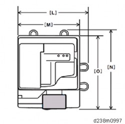
L | 668 mm / 26.29" |
M | 587 mm / 23.11" |
N | 738 mm / 29.05" |
O | 685 mm / 26.96" |
Model -27, -29, -65 (220–240 V)
Models equipped with the ARDF (W × D × H up to ARDF):
587 × 685 × 913 mm (23.2 × 27.0 × 36.0 inches)
Models equipped with the SPDF (W × D × H up to SPDF):
587 × 685 × 968 mm (23.2 × 27.0 × 38.1 inches)
Models with no ADF (W × D × H up to exposure glass):
587 × 685 × 788 mm (23.2 × 27.0 × 31.1 inches)
Model -17, -18 (120–127 V)
Models equipped with the ARDF (W × D × H up to ARDF):
587× 685 × 913 mm (23.2 × 27.0 × 36.0 inches)
Installation
Insert the plug firmly in the outlet.
Do not use an outlet extension plug or cord.
Ground the machine.
Input Voltage Level
Destination | Power supply voltage | Rated current consumption | Permissible voltage fluctuation |
NA | 120 to 127 V | 12 A or more | Image quality guaranteed: 108 V (120 V - 10%) to 138 V (127 V + 8.66%) Machine operation guaranteed: 102 V (120 V - 15%) to 138 V (127 V + 8.66%) |
EU | 220 to 240 V | 10 A | Image quality guaranteed: 198 V (220 V - 10%) to 264 V (240 V + 10%) Machine operation guaranteed: 187 V (220 V - 15%) to 276 V (240 V + 15%) |
AP | |||
CHN |
In order to increase the security of the MFP, and to ensure that the customer sets the administrator password, an administrator set/change prompt display is shown up at the first power-up.
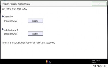
The following Program/ Change Administrator screen is displayed at the first power-up.

When the customers set the administrator/supervisor login password, the display disappears and the home display will appear. The customers, however, can erase this screen with the following procedure in the case that they think there is no need to set the password.
On the Program/Change Administrator screen, press [Change] next to Supervisor and then press [OK] without inputting any password.
Press [OK] again when the Confirm password display shows up.
For Administrator 1, do the same procedure as steps 1 and 2.
Press the [OK] button, and then turn the power OFF/ON.
SP5-755-002 (Display Setting: Hide Administrator Password Change Scrn) allows you to skip this screen temporarily and continue the installation procedure without setting an administrator password. However, the Program/Change Administrator screen appears every time you turn the power OFF/ON, if the password is not set.
For more details about this security issue, see "Notes on Using Multi-Function Printers Safely" supplied with the MFP.
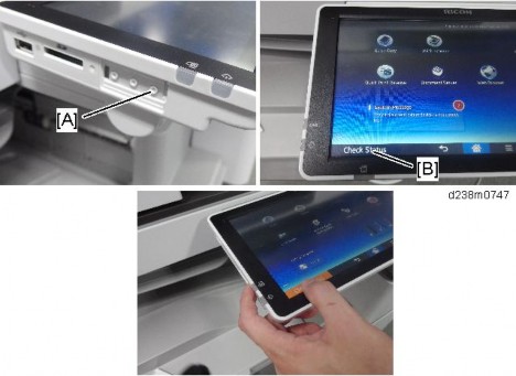
To enter the SP mode, there are two ways to display the number keyboard on screen;
Press the "Document Server" icon.
Press and hold the button [A] located at the left side of the operation panel and "Check Status [B]" at the same time.
Installation


Put the machine on the paper feed tray (1 tray/2 trays) first, then install the machine and other options.
You need Paper Feed Unit PB3220/PB3210 (D787) to align the paper transport path if you want to install Booklet Finisher SR3220 (D3B9).
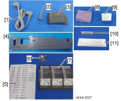
No. | Description | Q’ty |
1 | Power Cord | 1 |
2 | Cap for scanner lock | 2 |
3 | End Fence | 1 |
4 | Image Transfer Front Cover | 1 |
No. | Description | Q’ty |
5 | Decal - Paper Tray | 1 |
6 | Decal - Original Table for DF | 1 |
7 | Decal - Caution : Original : Multi Language | 1 |
8 | Cleaning Cloth | 1 |
9 | Cleaning Cloth Holder | 1 |
10 | Plate – Logo (Smart Operation Panel) | 1 |
11 | Plate – Logo (front cover) (for NA, EU, AA) | 1 |
- | M3x8 Screws for Image Transfer Front Cover | 2 |
- | Sheet: Safety (EU only) | 1 |
- | CD-ROM – OI (AA only) | 1 |
- | CD-ROM - Driver | 1 |
- | Sheet: Exposure glass | 1 |
- | Start Guide | 1 |
- | Read This First | 1 |
- | Sheet: EULA | 1 |
- | Seal: Caution | 1 |
- | Sheet: EMC address (EU only) | 1 |
- | Caution: Smart Operation Panel | 1 |
- | Caution: Smart Operation FCC (NA only) | 1 |
- | Caution: CE (EU only) | 1 |
- | NFC Tag | 1 |
- | Bluetooth decal (for NA, EU, AA) | 1 |
Installation

Remove the tape from the development units before turning the main power ON. The development units can be severely damaged if the tape is still attached.
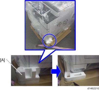
Removal of Packing Materials and Shipping Retainers
Remove the machine from the box, and check the items in the package.
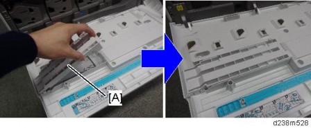
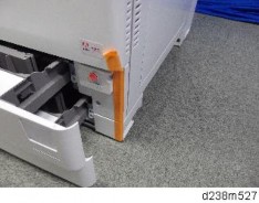
Remove the retainer [A] at the lower front right before lifting up the machine, because the handle for lifting the machine is hidden by the retainer [A].

Installation
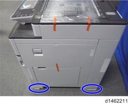
When you lift the machine, hold the correct parts, as shown in the photo below.

Do not hold any other parts of the machine when lifting it, because this might deform the machine or break the exterior covers
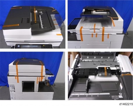
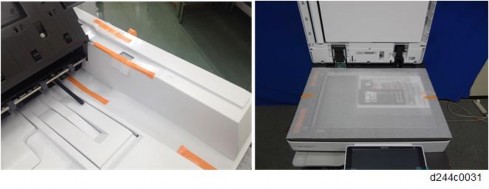
Remove the orange tapes and retainers on the outside. For a basic model

For a model on which SPDF DF3100 is preinstalled, remove the orange tapes and retainers on the SPDF.

Installation
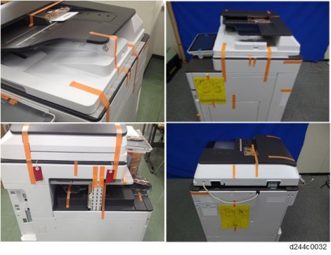
For a model on which ARDF DF3090 is preinstalled, remove the orange tapes and retainers on the ARDF.


Remove the paper size decal [A] on the exposure glass.

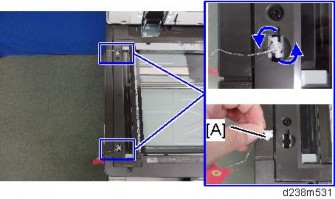
Remove the orange tapes on the scanner shipping locks.

Remove the two scanner shipping locks [A] by rotating them 90 degrees counter clockwise.
SC120 is displayed when the machine is turned ON with the shipping lock attached.

Keep the scanner shipping locks with the machine. They must be used when transporting the machine to another location. (page 2-36 "Moving the Machine")
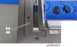
Attach the two caps [A] provided with the machine.

Installation
Pull out the 1st/2nd paper trays, remove the orange tape.

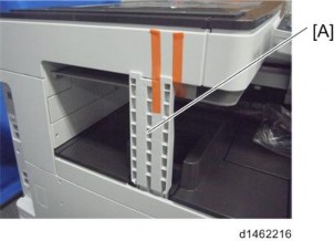
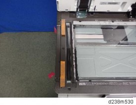
Remove the scanner support [A].

Open the front cover, and store the scanner support [A] in the storage location.

Underneath the bracket [A] is the storage location for the factory setting sheet.
For Machines with preinstalled SPDF: Removal of protective sheet
Open the SPDF.
Release the lever [A], open the pressure plate sheet [B], and pull out the protective sheet [C] slowly.
Remove the filament tape [D].

Close the pressure plate sheet [A].

Close the SPDF.
If the protective sheet remains in the SPDF, a paper jam will be detected.
Removal of PCDU Seals
Automatic initial adjustment will be done even if the seal was not removed correctly. But toner from a PCDU that still has the seal will not be able to reach the ITB, and will not be transferred to printouts and copies.
If this happens, remove the PCDU seal and do SP2-111-004 (Forced Line Position Adj. Mode d).
White stripes may appear in the printed images for the first 20k pages printing continuously in a low humid environment, due to the deviation of toner density
Installation
adjustment. Except for that, the machine operates normally.
SP descriptions
SP2-111-004 (Forced Line Position Adj. Mode d)
Executes the fine line position adjustment and rough line position adjustment.
Open the front cover.
Pull out the seals [A] for Y, M, C, and Bk.

Rotate the ITB contact lever [A] clockwise, and set it to the position in the following picture.

Attach the image transfer front cover [A] with the two screws (M3×8; provided with the accessories).

Close the front cover.
Attaching the Optical Cloth Pocket
Clean the adhesive surface of the optical cloth pocket with an alcohol-soaked cloth.
Attach the optical cloth pocket [A] to the left side of the scanner and put the optical cloth into the pocket.

Attaching the Paper Exit Tray Parts
1. Attach the part [A] to the paper exit tray.
First, insert and attach the front pin (inside the blue circle).

Installation
Checking the Position of the Paper Exit Feeler
Check the following points for the paper exit feeler [A] installed at the paper exit.
It can move in line with the ejection of paper.
It holds contact with the surface of the ejected paper and is still movable.

Paper will get jammed in the following cases.
The paper exit feeler does not function due to obstacles (such as cables).
The paper exit feeler does not function when the paper is pulled out and pushed back again.

Attaching the Decals
Attach the following decals provided with the machine accessories.

1: Original Set Decal 2: ADF Caution Decal
3: Paper Size Tray Number Decal
4: Brand Logo for Smart Operation Panel 5: Brand Logo for Front cover
Location for each decal

Toner Bottle Installation and Login Password Setting
Open the front cover.
Shake the toner bottle (Bk) 7 to 8 times.
Remove the toner bottle protection cap [A].

Push the toner bottle into the machine slowly.

Installation
Set the toner bottles (Y, M, and C) in the same way.
Close the front cover.
Connect the power cord to the machine.
Use the power cord that is provided with the machine. Do not use any other power cord. Also, do not use an extension cord.
Turn ON the main power.
Toner Initialization starts. It takes about 5 minutes to fill the toner up.
Be sure to wait long enough. If you do not, Auto Color Calibration (ACC) will take longer.
Password change display appears. If you want to skip this screen, SP5-755-002 (Display Setting: Hide Administrator Password Change Scrn) allows you to skip it. Refer to page 2-6 "Important Notice on Security Issues".
When Supervisor/ Administrator 1-4 passwords are configured via network, the "Change Supervisor login password" window will not display.
The passwords for supervisor or administrator 1 to 4 can be set via "System Settings". But the Program/Change Administrator screen appears every time the power switch is turned ON if the passwords are input this way. So we recommend the customers to set the passwords via network or the Program/Change Administrator screen.
Press [Change] and change the supervisor login password.

Input the password, and then press [OK].
Confirm the password, and then press [OK].
Change the administrator 1 login password.

Input the password, and then press [OK].
Confirm the password, and then press [OK].
After the toner initialization is completed, the machine beeps, and the following message is displayed. Turn the machine OFF/ON.

Even though the control panel display has gone off, the machine may still be on. So when turning the power off and back on, be sure to check that the main power indicator has gone off before turning the power on again.
Installation
For Machines with Preinstalled ARDF: Fax Stamp Installation (Option)
This procedure is required for the machine which the fax function is installed as standard.
Open the ARDF original cover and stamp holder [A].

Install the fax stamp [A] provided with the machine.

Close the holder.

Make sure that it is pushed in to the position where the marks on the holder and the exterior cover face each other. If not, jam detection (001) will occur.
Before Test
Perform the image quality test after installing all peripherals
Confirm that there are no accessories (such as screws and clamps) left inside the main machine and peripherals
Loading Paper
Turn ON the main power.
Check that the operation panel shows "No Paper" under the "Check Status" screen.
The paper size is basically detected automatically.
Pull out the paper feed tray slowly until it stops.
Load the paper.
While pressing the release lever, adjust the side fence to the paper size to be set.
Set the back fence.
ACC Execution and Color Registration Adjustment
If not transferred to printouts, the PCDU seals will not be removed correctly. Remove the PCDU seals, and then execute SP2-111-004 (Forced Line Position Adj. Mode d).
Do the "Automatic Color Calibration (ACC)" for the copier mode & printer mode as follows:
- Copier mode -
"User Tools" icon > "Machine Features" > "Maintenance" > "Auto Color Calibration" > "Copier Function" > "Start"
Press "Start Printing".
Put the printout on the exposure glass.

Put 10 sheets of white paper on the test chart. This ensures the precise ACC adjustment.
Close the SPDF/ARDF or the platen cover.
Press "Start Scanning" on the LCD. Then, the machine starts the ACC.
- Printer mode -
"Printer Function" > "Start"
Select a test pattern.
Print each ACC test pattern. There are 5 test patterns as follows: Test Pattern 1: 600x600 dpi
Test Pattern 2: 1800x600 dpi Test Pattern 3: 9000x600 dpi
Installation
Test Pattern 4: 1200x1200 dpi Test Pattern 5: 3600x1200 dpi
Press "Start Printing".
Put the printout on the exposure glass.

Put 10 sheets of white paper on the test chart. This ensures the precise ACC adjustment.
Close the SPDF/ARDF or the platen cover.
Press "Start Scanning" on the LCD. Then, the machine starts the ACC.
Repeat steps 1 to 7 until all the ACC test patterns have been printed.
Exit the User Tools mode.
Press the “Document Server” icon.
Or press and hold the [A] key and "Check Status [B]" at the same time until the number keyboard screen is displayed.
Enter the key code for SP mode.

Perform line adjustment.
Execute SP2-111-004 (Forced Line Position Adj. Mode d)
The result can be checked with SP2-194-007 (MUSIC Execution Result) 0: Success, 1: Failure
If failure, execute SP2-111-004 once more and check the result again.
Fix the color registration errors, referring to page 4-233 "Judgment for Type of Color Registration Error".
Also, results for each color can be checked with SP2-194-010 to 013 (MUSIC Execution Result: Error Result C, M, Y, K).
1: Completed successfully
Exit the SP mode. SP descriptions
SP2-111-004 (Forced Line Position Adj. Mode d)
Executes the fine line position adjustment and rough line position adjustment.
SP2-194-007 (MUSIC Execution Result: Execution Result)
Displays the result code of MUSIC adjustment. 0: Success
1: Failure
SP2-194-010 to 013 (MUSIC Execution Result: Error Result C,M, Y, K)
Displays the result code of MUSIC adjustment for each color. 0: Not done
1: Completed successfully 2: Cannot detect patterns
3: Fewer lines on the pattern than the target 4: Out of the adjustment range
5 to 9: Not used
Installation
Checking the Copy Image with the Test Chart
Make a copy of a test chart and check the output quality.
Paper Settings
Adjusts the side-to-side registration, refer to the “Image Adjustment” > “Registration” section.
1. Enter SP2-109-003.
Print out the test pattern (14: Trimmed area) with SP2-109-003.
If necessary, adjust the registration for the paper feed tray.
SP1-002-001 (Side-to-Side Registration: By-pass Tray)
SP1-002-002 (Side-to-Side Registration: Paper Tray 1)
SP1-002-003 (Side-to-Side Registration: Paper Tray 2)
SP1-002-006 (Side-to-Side Registration: Duplex)
If optional paper trays is installed, do the following SPs as well:
SP1-002-004 (Side-to-Side Registration: Paper Tray 3)
SP1-002-005 (Side-to-Side Registration: Paper Tray 4)
If necessary, adjust the registration for ADF.
SP6-006-001 (ADF Adjustment: Side-to-Side Regist: Front)
SP6-006-002 (ADF Adjustment: Side-to-Side Regist: Rear)
If necessary, adjust the registration for Scanner.
SP4-803-001 (Home Position Adj Value)
SP4-011-001 (Main Scan Reg)
SP descriptions
SP1-002 (Side-to-Side Registration)
Adjusts the side-to-side registration by changing the laser main scan start position for each mode and tray.
Increasing a value: The image is moved towards the rear edge of the paper. Decreasing a value: The image is moved towards the front edge of the paper.
SP2-109-003 (Test Pattern: Pattern Selection)
Selects the test pattern.
Auto Remote Firmware Update Settings
Specify ARFU settings as required.
Operating Conditions:
Use the machine in an environment where it can be connected to the Internet.
Auto remote firmware update (ARFU) requires connection to an external network. Be sure to get permission from the customer before setting ARFU up.
The connection is one-way, so the user’s data cannot be accessed from the global server.
Pre-Operation Set Up and Checks
Check the network settings (IP address, Subnetmask, Gateway, and Proxy).
Check the DNS setting.
How to Check the DNS setting
Get the IP address of the DNS server from the customer.
Request the customer to check the DNS server.
How to check the address of the DNS server by the PC (reference). Check by either of the following methods:
Run "ipconfig / all" at the command prompt on the PC, then check the IP address of the DNS server.
Open the IPv4 properties screen in the PC, check the IP address setting of the DNS server is whether manual or automatic.
If the access to the external server is restricted, request the network administrator (customer) to permit the following FQDN name for communication.
- FQDN: p-rfu-ds2.support.ricoh.com
Ask the customer the prohibited time and day of the week of ARFU execution.
Check SP5-816-087 (Remote Service: CERT:Macro Ver) and make sure the encryption level is 2048 bit.
[1]: 512 bit / [2]: 2048 bit
If SP5-816-087 is [1]: 512 bit, specify the settings as follows:
Initialize the encryption level by executing SP5-870-003 (Common Key Info Writing: Initialize)
Rewrite as 2048 bit in SP5-870-004 (Common Key Info Writing: Writing 2048 bit).
Turn off and on the main switch.
Installation
ARFU uses the same certificate as @Remote to communicate with the Global Server. This may cause failure in connecting with the Center Server, if the device is to be installed in the following conditions. Make sure to check the conditions before changing the encryption level and do the corresponding workaround.
Conditions
Customer uses RC Gate Type BN1.
RC Gate Type BN1 does not support 2048 bit encryption level communication with Ricoh devices (HTTPS Managed device). Therefore, device cannot be registered under RC Gate Type BN 1 in this case.
Ricoh device (HTTPS Managed) that supports only 512 bit encryption level is registered as external appliance.
Only one encryption level can be set for an external appliance for its communication with imaging devices. If a 512 bit encryption level Ricoh device (HTTPS Managed) is registered, the external appliance as well as other devices must also use 512 bit encryption level even if 248 bit encryption is supported on those devices.
Workaround
For Condition 1:
Advise your customer to change to the latest appliance that supports 2048 bit encryption level communication.
For Condition 2:
Manage the device with embedded RC Gate. (2048 bit)
Exclude non-supported devices from the external appliances, and then, change the encryption level of external appliance and all managed devices (from 512 bit to 2048 bit). Devices excluded to be registered with embedded RC Gate. (512 bit)
Configuration Procedure
Do interface settings.
In User Tools > Machine Features > System Settings > Interface Settings, specify the machine’s IPv4 address, subnet mask, and gateway IPv4 address.
Do DNS settings and check the connection.
In User Tools > Machine Features > System Settings > Interface Settings > DNS Settings
If the setting of the DNS IP address is automatic, select [Auto-Obtain (DHCP)] at the MFP machine's DNS settings.
If the setting of the DNS IP address is manual, select [Specify] and specify the DNS server 1 to 3.
Press [Connection Test] to check the connection with the input address. Make sure that it is connected successfully.

Check the user’s network environment and, as required, specify the proxy server settings in the following SPs:
SP5-819-062 (Use Proxy DFU(SSP)) 1: Use / 0: Not use
SP5-816-063 (Use Proxy DFU(SSP))
SP5-816-064 (Proxy Port Number)
SP5-816-065 (Proxy User Name)
SP5-816-066 (Proxy Password)
They can be specified also via Web Image Monitor from Device by logging in with the administrator authorization. Management>Configuration>Device Setting>Auto Firmware Update.
“Auto Firmware Update" will appear on Web Image Monitor if SP5-886-111(AutoUpdateSetting) is set to "1(ON)."
Set SP5-886-111 (AutoUpdateSetting) to "1(ON)."
To download the firmware only using SFU, and not by ARFU, specify the settings as follows:
SP5-886-111(AutoUpdateSetting) to "0 (OFF)"
SP5-886-115 (SfuAutoDownloadSetting) to "1 (ON)"
Set the prohibited day of the week, and time, of the auto firmware update.
Consider usages of customer’s MFP, change the following as needed.
SP5-886-112 (AutoUpdateProhibitTermSetting) 0: OFF, 1: ON (Default )
SP5-886-113 (AutoUpdateProhibitStartHour) Default: 9
SP5-886-114 (AutoUpdateProhibitEndHour) Default: 17
SP5-886-120 (AutoUpdateProhibitDayOfWeekSetting) Default: 0x00
Installation
Set the bits for the days of the week to prohibit updating. Prohibited (Monday - Sunday): Bit 7
Monday: bit 6
Tuesday: bit 5
Wednesday: bit 4
Thursday: bit 3
Friday: bit 2
Saturday: bit 1
Sunday: bit 0
e.g.) Prohibited on Mon., Fri., Sat., and Sun.: 0x47 (01000111)
They can be specified also via Web Image Monitor logged in as the machine administrator from Device. Management>Configuration>Device Setting>Auto Firmware Update.
“Auto Firmware Update" will appear on Web Image Monitor if SP5-886-111(AutoUpdateSetting) is set to "1(ON)."
Use the machine with its main power on and connected to the Internet. Checking the ARFU Connection
Enter the SP mode.
Press [Firmware update].
Press [Update].
Press [Execute update].
”Execute update” appears even if @Remote connection has not been established.
If an error code appears when you click “Execute update”, the machine is in the following status.
Error code | Status |
E51 | The machine in operation for printing, etc. |
E71 | Network connection error |
(Other error, see page 5-16 "Error Screens During Updating")
Check if one of the following messages appears: "Will you download the latest package Ver *** and update?" or "The installed package is the latest version.".
If the message appears, it is possible to execute ARFU.
->Press “No” and close SP mode to complete the configuration.
If the message does not appear, it is not possible to execute ARFU.
->Check the network settings again.
Update will run immediately if you press “Yes” at the message "Will you download the latest package Ver *** and update?" Update cannot be canceled, as it is run by SFU. (Update can be canceled for ARFU.)
If the access to the global server is restricted, request the network administrator (customer) to permit the following FQDN name for communication.
- FQDN: p-rfu-ds2.support.ricoh.com
SP5-886-116 (Auto Update Prohibit Term Setting) displays the scheduled date and time of the next ARFU.
If the scheduled date and time of the next ARFU coincides with a time and day of the week when ARFU is prohibited, the machine sends an inquiry to the server to check if there is a new firmware package at this time. If there is a new firmware package, it is downloaded in the background, but the package updating is cancelled and executed on the next occasion, 76 hours later, to update the package.
Specifying the Time and Day of the Week to Prohibit Updating via Web Image Monitor
Start the Web Image Monitor.
Log in as the machine administrator.
Point to [Device Management], and then click [Configuration].
Installation
Click "Auto Firmware Update".

Turn the main power OFF and back ON again after setting SP5-886-111 (AutoUpdateSetting) to "1(ON)". "Auto Firmware Update" will appear in the menu list of the Web Image Monitor.
In the applicable items, specify the times and days of the week to prohibit updating.
Select the check boxes of the applicable days of the week to prohibit updating on that day

Enabling the Copy Data Security Function
The Copy Data Security function is installed in the IPU as standard for this machine. Enable this function in User Tools when installing the machine.
Press [User Tools] icon on the HOME screen.
Select [Machine Features] > [System Settings] > [Administrator Tools] > [Detect Data Security for Copying] > "On".
Copy Data Security Function
If the Unauthorized Copy Prevention function is enabled, embedded text patterns (for instance, a warning message such as "No Copying") are displayed when documents are copied illegally. Accordingly, unauthorized copying can be prevented.
If the Data Security for Copying function is used and settings for special patterns embedded in documents are enabled, copies of documents with embedded patterns are printed with gray overprint. Accordingly, information leakage can be prevented. To protect documents by gray overprint, the Data Security for Copying function must be enabled on the copier or multi-function printer.
HDD Security Function Setting
Perform the encryption and overwrite settings to protect the user information in the HDD as necessary.
Follow the instructions in page 2-278 "Security Settings".
Settings Relevant to the Service Contract
Change the necessary settings for the following SP modes if the customer has made a service contract.
SP No. | Function | Default |
SP5-045-001 Counter method | Specifies if the counting method used in meter charge mode is based on developments, prints, or coverage. | "1": Prints |
SP5-104-001 (SSP) A3/DLT double count | Specifies whether the counter is doubled for A3/DLT paper. | "0":Single counting |
SP5-812-001 and -002 Service Tel: Telephone / Facsimile | -001: shows or sets the telephone number of the service representative. -002: shows or sets the fax number of the service station. The number is printed on the counter list when the "Meter Click Charge" is enabled. User can send a fax message with the counter list. | |
Installation
Counter Display Method
There are 3 types (Developments, Prints and Coverage). Display mode can be set by SP5-045-001 (Accounting counter: Counter Method).
Value | Mode | Descriptions |
0 | Development Count | YMC Development Counter Bk Development Counter |
1 | Print Count (Default) | Color Copy Counter B&W Copy Counter Color Print Counter B&W Print Counter Color Total Counter B&W Total Counter |
2 | Coverage Count | Color Total Counter B&W Total Counter Color Coverage Counter 1 Color Coverage Counter 2 Color Coverage Counter 3 |
Value | Mode | Descriptions |
7 | Coverage Count (YMC) | Color Total Counter B&W Total Counter Color Coverage Counter 1 (YMC) Color Coverage Counter 2 (YMC) Color Coverage Counter 3 (YMC) |
Installation is now completed.
This section shows you how to manually move the machine from one floor to another floor. Before turning off the main power, make sure 100% is shown as available memory on the screen if the fax option is installed.
Turn off the main power.
Disconnect the power plug from the outlet.
Close all covers and paper trays, including the front cover and bypass tray.

Move the scanner carriage to the correct position [A] with SP4-806-001 (SSP), and reattach the scanner shipping locks with lock position [B].
Keep the machine level and carry it carefully, taking care not to jolt or tip it, and protect the machine from strong shocks.
When moving the machine, do not press against the ADF.
Remove the optional feed tray when lifting the main machine for moving it to another floor.
SP descriptions
SP4-806-001 (Scanner carriage storage operation) (SSP)
Moves the scanner carriage to the shipping lock position. Attach the scanner shipping locks and fix the scanner carriage after executing SP4-806-001.
Installation
Do not push the center part of the rear cover. Do not hold the covers of the stabilizers.
Do not put hard pressure on the rear cover [A] when moving or picking up the machine as it is fragile. This also applies to the operation panel [C]. Hold part [B] when moving the machine.
Hold 4 corners on the bottom base when holding the machine with the optional paper feeding tray joined to the main machine. Do not hold any other parts.

Cautions upon Lashing
Position the machine so that its left side faces the wall. Make sure to put cushioning in between.
Fasten the belt at the ridge line with cushioning.
Make sure that the belt is over the front cover (at 45 – 75 cm height from the ground).

Installation
Unplug the machine power cord before starting the following procedure.
Do the following procedure not to damage any harnesses.
Check that harnesses are not damaged or pinched after installation.
This option is provided as a service part.
If you want to install Anti-Condensation Heater (Scanner), (1) heater for scanner and (2) electrical components should be ordered.
Accessory Check
Heater for Scanner
No. | Description | Q’ty | Remarks |
1 | COVER: HEATER: SCANNER | 2 | Parts Number: |
2 | HEATER:120V:9W HEATER:230V:9W | 1 | |
3 | BRACKET HEATER: SCANNER | 1 | |
5 | SCREW:POLISHED ROUND/SPRING:M4x8 | 1 | |
6 | SCREW M3x3 | 2 |
NA (120V): D2380071
EU/AA (220/240V): D2380072
Electrical components
No. | Description | Q’ty | Remarks |
- | TAPPING SCREW M3X6 | 3 | Parts Number: |
D2386650 | |||
4 | CLAMP | 6 | |
Electrical parts set for Scanner | |||
- | HARNESS: SCANNER/PCU | 1 | and Drum heater is common |
between NA/EU | |||
- | PCB: DHB | 1 | |
- | HARNESS :DC: DHB | 1 | |
- | HARNESS :AC: DHB | 1 |
Installation
Installation Procedure
Remove the rear cover [A].
Remove the rear lower cover [A].
Remove the power supply box [A] ![]() x6, Among them, tapping screw x1)
x6, Among them, tapping screw x1)

Release the 5 clamps.
Remove the HVP-CB with bracket [A] (Hook x2).

Installation
Connect the combined Blue/White harness to the back frame [A].
The harness will be connected to the relay board. See the details in step 8.
Reinstall the HVP-CB unit and power supply box.

Secure the relay board to the main machine and connect the Blue/White harness to the socket on the board ![]() × 1,
× 1, ![]() × 3).
× 3).
Connect the harnesses on the relay board to the sockets on the PSU.
Two types of harnesses are packed with the heater. Both the Blue/White one [A] and the Gray one [B] must be connected as shown below.
Remove the right rear cover [A] ![]() x4, among them, tapping screw x1)
x4, among them, tapping screw x1)

Remove a screw.

Installation
Remove the scanner right cover [A].
Remove the hook at the upper part, and then slide the cover in the rear direction.

Route the harness around the outside of the PSU and pull the harness out of the electrical box through the hole [A] ![]() x 4).
x 4).
Route the harness in the direction of the scanner ![]() x 6).
x 6).

Fasten the clamp between the bindings of the harness at the location indicated by the red circle.
Attach the connector to the frame.
Connect it to the heater harness in step 25.

Remove the scale [A]