Replacement and Adjustment
Controller cover (page 4-10)
Controller box cover (page 4-182)
Bracket [A]

Controller box [A]
Controller cover (page 4-10)
Controller box cover (page 4-182)
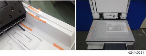
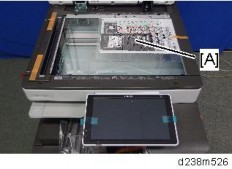
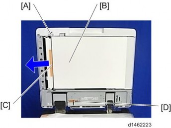
Disconnect the FFC [A] between IPU-Scanner Unit while pressing the lock release button.

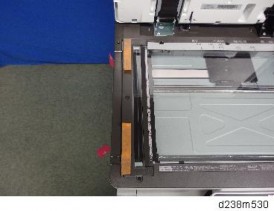
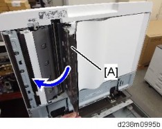
Open the controller box [A].

Imaging IOB [A]
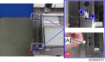
Disconnect the FFC while pressing the lock release levers on its sides. Disconnecting the FFC without releasing the lock may cause the FFC or connector to be damaged, resulting in an SC670 error.
Replacement and Adjustment

Controller cover (page 4-10)
Controller box cover(page 4-182)
Disconnect the FFC [A] between IPU-Scanner Unit while pressing the lock release button.

Open the controller box [A].

HVP_TTS [A]

Replacement and Adjustment
Turn off the main power switch and unplug the power cord before replacing the PSU.
Do not touch the areas outlined in red in the following diagrams when replacing the PSU. Residual charge on the board may cause electric shock.

Rear lower cover (page 4-15)
PSU (AC Controller Board) [A]

Turn OFF the main power switch and unplug the power cord before replacing the PSU.
Do not touch the areas outlined in red in the following diagrams when replacing the PSU. Residual charge on the board may cause electric shock.
100V | 200V |
|
|
Rear lower cover (page 4-15)
PSU (DC Power) [A]

Replacement and Adjustment
Rear lower cover (page 4-15)
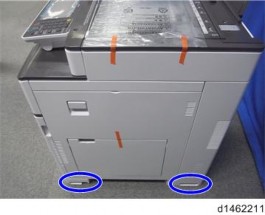
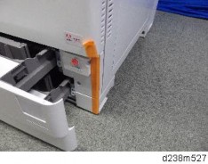
Power supply box [A] ![]() x6, Among them, tapping screw x1)
x6, Among them, tapping screw x1)

You can hang the power box [A] on the machine by using 3 tabs.

Power supply box (page 4-203)
Paper transport IOB [A]

Power supply box (page 4-203)
HVP_CB [A]

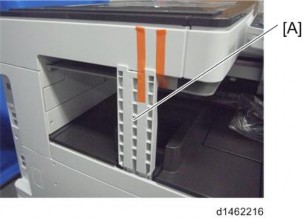
HVP-CB with Bracket
Power supply box (page 4-203)
Release the 5 clamps.

Replacement and Adjustment
Remove the HVP-CB with bracket [A] (Tab x2)


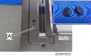
Front upper cover (page 4-17)
Proximity sensor (Human detection sensor) board [A].

Replacement and Adjustment
Adjustment before Replacing the Dust Filter
Before replacing the Dust filter, set SP3-701-132 to "1" and switch the power OFF. Then replace the Dust filter and switch the power ON.
Replacement
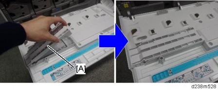
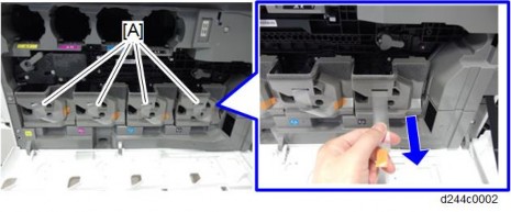
Pull out the ozone filter and dust filter box [A].

Ozone filter [A], Dust filter [B]

When attaching the ozone filter and dust filter unit to the machine, attach it by pressing the area below its center [A]. Attaching it by pressing the area above the center may cause incomplete attachment.

Deodorization filter box [A]

Deodorization filter [A]

Replacement and Adjustment
Inner lower cover (page 4-24)
Development intake fan unit [A]

Development intake fan [A]

Power supply box (page 4-203)
Ozone exhaust fan [A]

Front upper cover (page 4-17)
Paper exit cooling fan [A]

Replacement and Adjustment
Rear cover (page 4-14)
Right rear cover (page 4-16)
Fusing exhaust fan unit [A]

Fusing exhaust fan [A]

Rear cover (page 4-14)
Right rear cover (page 4-16)
Toner supply cooling fan unit [A]

Toner supply cooling fan [A]

Replacement and Adjustment
Rear lower cover (page 4-15)
PSU cooling fan unit [A]

PSU cooling fan [A]

Controller box cover (page 4-182)
Controller box cooling fan [A]

For the best image quality, this is done during installation, and should be done periodically by the customer. It is accessed with the user tools as follows.
User Tools -> Machine Features -> Maintenance -> Auto Color Calibration
When you set the adjustment sheet on the exposure glass, put about 10 pieces of white paper on the adjustment sheet in order for the original to contact the exposure glass sufficiently. Instruct the customer to periodically execute the ACC.

Description | |
[A] | Output adjustment sheets. You must execute both for copy and printer functions. |
[B] | Roll back to the previous value. |
[C] | Displays the last date/time ACC was executed. |
About the printer ACC
It is difficult to keep constant printing density due to the environment of the machine, individual differences between devices, and the passage of time. The printer ACC reads the current printing density using the scanner, and then compares the result with the time when it was in a normal state, and makes the printing density close to the normal state.
Issues possibly solved by the printer ACC
When the printed image looks strongly red, blue, or yellow because the density of the cyan, magenta, and yellow are not balanced.

Replacement and Adjustment
When the printed image looks too dark or light.

Issues cannot be solved by the printer ACC
The tone differences from other types of machine or machines of other manufactures cannot be solved by the printer ACC. The tone differences from the machines of other manufactures occur due to the differences in color reproduction caused by the difference in the engine and color profile specifications so it may not be solved even after performing the printer ACC. Refer to page 4-228 "Adjustment by Changing the Machine’s Profile Setting" for the color tone differences from the other types of the machine.
Check the printing registration/side-to-side adjustment and the blank margin adjustment before you do the following scanner adjustments.
Use a C4 test chart to do the following adjustments.
Scanner Sub-scan Magnification
A: Sub-scan magnification
Put the test chart on the exposure glass. Then make a copy from one of the feed stations.
Check the magnification ratio. Adjust with SP4-008 if necessary. Standard: ±1.0%.
Scanner Leading Edge and Side-to-side Registration

A: Leading Edge Registration
Put the test chart on the exposure glass. Then make a copy from one of the feed stations.
Check the leading edge and side-to-side registration. Adjust the following SP modes if necessary.
Standard: 0 ± 2mm for the leading edge registration, 0 ± 2.5mm for the side-to-side registration.
What It Does | SP code |
Leading edge registration (Home Position Adj Value) | SP4-803-001 |
Side-to-Side Registration (Main Scan Reg) | SP4-011-001 |
Replacement and Adjustment
ARDF Side-to-side, Leading Edge Registration and Trailing Edge

A: Leading edge registration
Use A3/DLT paper to make a temporary test chart as shown above.
Put the temporary test chart on the ARDF. Then make a copy from one of the feed stations.
Check the registration. Check the leading edge and side-to-side registration. Adjust the following SP modes if necessary.
Standard: 4.2 ± 2 mm for the leading edge registration, 2 ± 1 mm for the side-to-side registration. Use the following SP modes to adjust if necessary.
SP Code | What It Does | Adjustment Range |
SP6-006-001 | Side-to-Side Regist: Front | ± 3.0 mm |
SP6-006-003 | Leading Edge Registration | ± 5.0 mm |
SP6-006-005 | Buckle: Duplex Front | ± 3.0 mm |
SP6-006-006 | Buckle: Duplex Rear | ± 2.5 mm |
SP6-006-007 | Rear Edge Erase (Trailing Edge) | ± 10.0 mm |
ARDF Sub-scan Magnification
Put the temporary test chart on the ARDF. Then make a copy from one of the feed stations.
Check the magnification ratio. Adjust with SP6-017-001 if necessary.
Standard: ±5.0%
Reduction mode: ±1.0%
Enlargement mode: ±1.0%
Image Area

A = C = 5.2 mm (0.2"), B = 2.0 mm
Make sure that the registration is adjusted within the adjustment standard range as shown below.
Leading Edge
Adjusts the leading edge registration for each paper type and process line speed.
Side to Side
Adjusts the side-to-side registration for each paper feed station. Use SP mode (SP1-002) to adjust the side-to-side registration for the optional paper feed unit, LCT, and duplex unit.
Adjustment Standard
Leading edge (sub-scan direction): 5.2 ± 2 mm
Side to side (main-scan direction): 2 ± 1 mm
Paper Registration Standard
The registration in both main- and sub-scan directions can change within the following tolerance.
Sub-scan direction: 0 ± 9 mm
Main-scan direction: 0 ± 4 mm
Replacement and Adjustment
Adjustment Procedure
1. Enter SP2-109-003.
Print out the test pattern (14: Trimmed area) with SP2-109-003.
Registration can change slightly as shown on the previous page. Print some pages of the "14: Trimmed area" for step 3 and 4. Then average the leading edge and
side-to-side registration values, and adjust each SP mode.
Do the leading edge registration adjustment.
Check the leading edge registration and adjust it with SP1-001.
Select the adjustment conditions (paper type and process line speed).
Input the value. Then press the ![]() key.
key.
Generate a trim pattern to check the leading edge adjustment.
Do the side-to-side registration adjustment.
Check the side-to-side registration and adjust it with SP1-002.
Select the adjustment conditions (paper feed station).
Input the value. Then press the ![]() key.
key.
Generate a trim pattern to check the leading edge adjustment.
Adjust the erase margin C and D only if the registration (main scan and sub scan) cannot be adjusted within the standard values. Do the registration adjustment after adjusting the erase margin C and D, and then adjust the erase margin A and B.

1. Enter SP2-109-003.
Print out the test pattern (14: Trimmed area) with SP2-109-003.
Check the erase margin A and B. Adjust them with SP2-103-001 to -015 if necessary.
Leading edge: 0.0 to 9.0 mm (default: 4.2 mm)
Side-to-side: 0.0 to 9.0 mm (default: 2.0 mm)
Trailing edge: 0.0 to 9.0 mm (default: 4.2 mm)
If a customer wishes to have the tone of the printed image corrected, you can adjust it as follows. For details about the adjustment procedures, see the corresponding sections.
Adjustment Method | Outline |
Adjustment by Changing the Printer Driver Setting (page 4-221) | Perform this to adjust the tone for each print job. This can be adjusted by the user. |
Adjustment by Changing the Machine’s Profile Setting (page 4-228) | Perform this to make the tone similar to that of another model. Doing this changes the tone of all images printed by the machine’s printer function. |
Adjustment by Printer Gamma Correction (page 4-230) | Basically, we recommend the default setting. Doing this changes the tone of all images printed by the machine’s printer function. |
Replacement and Adjustment
Using the printer driver, you can change the color balance for each print job as follows.
Open the printer driver’s "Color Balance Details" window. (page 4-221)
Adjust the tone (color gamut). (page 4-224)
Opening the Printer Driver's "Color Balance Details" Window
PCL6 driver / PS driver
Click [Detailed Setting] tab -> [Print Quality].
Click [Details...] in "Color Balance".

"Color Balance Details" window appears. (page 4-223) PCL6 Universal driver / PS Universal driver
Click [Detailed Setting] tab -> [Print Quality:Advanced].
Click [Details...] in "Color Balance".

"Color Balance Details" window appears. (page 4-223) Mac PS driver
On the print dialog box, open the context menu (right click menu), then select [Color Balance Details].
"Color Balance Details" window appears. (page 4-223)
Replacement and Adjustment
Color Balance Details Window
PCL driver
PS driver
Mac PS driver
Adjusting the Tone in the "Color Balance Details" Window
Brightness
Decreasing the brightness makes the printed image darker and increasing it makes the printed image fainter.
Decrease the value to make the printed image darker and increase it to make the printed image fainter.
If you increase the value too much, overexposure of bright areas may occur.
If you decrease the value too much, underexposure of dark areas may occur
Can be specified using the PCL/PS drivers.
Contrast
Increasing the contrast makes bright areas brighter and dark areas darker.
Decreasing the contrast makes bright areas darker and dark areas brighter.
Increase the value to make the printed image clearer and decrease it to prevent overexposure of bright areas and underexposure of dark areas.
If you increase the value too much, overexposure of bright areas and underexposure of dark areas may occur.
If you decrease the value too much, the printed image may become unclear.
Can be specified using the PCL/PS drivers.
Replacement and Adjustment
Saturation
Increasing the saturation makes the printed image more vivid.
Decreasing the saturation makes the printed image closer to the neutral color (gray).
If you increase the value too much, it may lower the gradation, resulting in a difficulty to distinguish colors.
The printer’s color gamut is limited, so even if you increase the value, it may not make any difference.
Can be specified using the PCL driver only.
RGB Adjustment (Adjust Each Color)
When using the PCL driver, adjust the tone (color gamut) by this method.
Increasing "Red" makes "M" and "Y" more vivid and "C" less so.
Decreasing "Red" makes "M" and "Y" less vivid and "C" more so.
Increasing "Green" makes "C" and "Y" more vivid and "M" less so.
Decreasing "Green" makes "C" and "Y" less vivid and "M" more so.
Increasing "Blue" makes "C" and "M" more vivid and "Y" less so.
Decreasing "Blue" makes "C" and "M" less vivid and "Y" more so.
CMYK Adjustment (Adjust Each Color)
When using the PS driver, adjust the tone (color gamut) by this method.
Adjustment Examples
The following shows adjustment examples. Be sure to check the printed image when changing values.
If the printed image is dark:
Increase the brightness by 20.
If the printed image is faint:
Decrease the brightness by 20.

Replacement and Adjustment
If the printed image is too bluish:
Increase "Red" or "Magenta" by 20.
If the printed image is too reddish:
Increase "Blue" or "Cyan" by 20.
If the printed image is unclear:
Increase the contrast by 15.

You can change the printer’s profile setting by specifying a bit switch in SP mode.
By changing the profile setting, you can change the tone of all images printed by the machine’s printer function.
By changing the profile setting, you can make the tone (image gamut) of the printed image similar to that of another model. However, due to factors such as the image gamut difference between different models, individual differences, and ageing of components, you may not achieve exactly the same tone.
Procedure to Change the Profile Setting
Enter the printer SP mode.
Change the values of bit switches with the following SP numbers.
Desired tone (color gamut) | SP to change | Value to select |
2009 Spring model or those before it | SP1-001-002 | 00000001 [01H] |
2009 Autumn to 2011 Spring model | 00010000 [10H] | |
2011 Autumn model or later | 00000000 [00H] | |
Fuji Xerox product | SP1-001-001 | 10000000 [80H] |
Turn the machine’s power off and then back on.
The specified setting is applied.
Replacement and Adjustment
Patterns and Tendency of the Tone for Each Profile
Model with the desired tone | Image (Photo) | Graphic (Chart) | Text |
2009 Spring model or earlier | Color A | Color A | Color A |
2009 Autumn to 2011 Spring model | Color B | Color B | Color B |
2011 Autumn model or later | Color B | Color C | Color C |
Fuji Xerox product | Color D | Color D | Color D |
Color A
Standard profile for MP C2030/C2050/C2030/C2530/C2800/C3300/C4000/C5000 and their preceding models
Color B
Standard profile for MP C2051/C2551/C3001/C3501/C4501/C5501. Compared to Color A, following changes have been applied:
Yellow tint of the skin color is reduced.
Redness is enhanced to prevent it from appearing like vermilion.
Green and blue-green appear darker.
Uses the pure cyan toner on graphics to prevent muddiness.
Pink in the printed image appears darker.
Color C
Standard profile for MP C3002/C3502/C4502/C5502 up to the present model.
Compared to Color B, the difference between colors have become more recognizable. On the other hand, the printed image has become slightly less vivid.
If you receive a comment that the printed image is less vivid compared to that of a Color B-standard model, we recommend changing the setting to Color B.
Color D
Profile with a tone similar to that of the prints by the FX products.
Bluish colors appear slightly purplish. (Image of the sky appears with a slight tint of red.)
Pink in the printed image appears with a tint of magenta.
We recommend that you keep the printer gamma correction values at the default values.
The values adjusted/saved in the printer SP mode are applied after the machine’s power is turned off and then back on.
After adjusting/saving the values in the printer SP mode, make sure not to perform the printer’s Auto Color Calibration (ACC). Doing so will reset the values.
To change multiple resolutions, perform this procedure for each resolution.
Select the mode you want to change in the printer SP1102-001: Resolution Setting.
1102 | [Resolution Setting] | ||
Selects the printing mode (resolution) for the printer gamma adjustment. | |||
001 | Resolution Setting | CTL | [0 to 9 / 0 / 1/step] 0: 1200x1200 Photo (2bit/4col) 1: 1200x1200 Photo (1bit/4col) 2: 600x600 Photo (4bit/4col) 3: 600x600 Photo (2bit/4col) 4: 600x600 Photo (1bit/4col) 5: 1200x1200 Text (2bit/4col) 6: 1200x1200 Text (1bit/4col) 7: 600x600 Text (4bit/4col) 8: 600x600 Text (2bit/4col) 9: 600x600 Text (1bit/4col) |
Change the gamma correction value for each color in the printer SP1104: Gamma Adjustment.
When adjusting the value, be sure to follow the sequence: I ![]() M
M ![]() S (Shadow)
S (Shadow) ![]() H (Highlight).
H (Highlight).
To lower the print density, reduce and save the H/M/S/I value for each color.
To heighten the print density, increase and save the H/M/S/I value for each color.
Replacement and Adjustment
1104 | [Gamma Adjustment] | ||
Adjusts the printer gamma for the mode selected in the "Mode Selection" menu. | |||
001 | Black: Highlight | CTL | [0 to 30 / 00 / 1/step ] |
002 | Black: Shadow | CTL | |
003 | Black: Middle | CTL | |
004 | Black: IDmax | CTL | |
021 | Cyan: Highlight | CTL | |
022 | Cyan: Shadow | CTL | |
023 | Cyan: Middle | CTL | |
024 | Cyan: IDmax | CTL | |
041 | Magenta: Highlight | CTL | |
042 | Magenta: Shadow | CTL | |
043 | Magenta: Middle | CTL | |
044 | Magenta: IDmax | CTL | |
061 | Yellow: Highlight | CTL | |
062 | Yellow: Shadow | CTL | |
063 | Yellow: Middle | CTL | |
064 | Yellow: IDmax | CTL | |
Gamma Correction Sheet

Range where each value affects

Execute the SP1105-001: Save Tone Control Value.
If you exit the SP mode without saving the values, any changes made in the printer SP1104: Gamma Adjustment will be lost.
You can check the color balance before and after the gamma adjustment in the printer SP1103-001: Test Page - Color Gray Scale.
Turn the machine’s power off and then back on.
The changed gamma correction setting is applied.
Check the output image and repeat steps 1 - 4 until the desired image is obtained.
Replacement and Adjustment
Adjust color registration with the following procedure when color registration errors occurred.
Check the Occurrence of Color Registration Errors
Prepare some A3 sheets.
Execute SP2-111-004 (Forced line Position Adj.: Mode d)
Make sure that execution completed successfully with using SP2-194-007 (MUSIC).
If the value of SP2-194-007 is "0", it indicates that the result of SP2-111-004 was successful. If the value of SP2-194-007 is "1", it indicates that the result of SP2-111-004 was a failure, which you need to fix the color registration errors (See "Ways to fix color registration errors" (page 4-233))
Execute SP2-109-003 (Test Pattern: Pattern Selection)
With a loupe, check the details of the color registration errors on the printed test pattern. (page 4-233)
Specification: Main/Sub is smaller than 180.0um
No color registration errors: Adjustment completed.
Color registration errors occurred: Adjust the color registration errors (See "Ways to fix color registration errors" (page 4-233)
Judgment for Type of Color Registration Error
In the following diagrams, solid lines represent "K" and dotted lines indicate any of "C", "M" or "Y".
Pattern 1
This is a case in which there is a shift in the sub-scan direction at the leading edge of the paper. The following diagram shows "C", "M" or "Y" lines closer to the leading edge than "K" lines.

Pattern 2
This is a case in which there is a shift in the sub-scan direction at the trailing edge of the paper. The following diagram shows "C", "M" or "Y" lines farther away from the leading edge than "K" lines.

Pattern 3
This is a case in which a color registration error is found in the main-scan direction and size of the error is the same at the left, center and right.

Pattern 4
This is a case in which a color registration error is found in the main-scan direction and the size of the error is different at the left, center and right. For "M", the largest error will be at the right, followed by the center and then the left. For "C" or "Y", the order will be reversed. This is because the writing direction of the laser beam for "K" and "M" is different from "C" and "Y". Case "M"

Replacement and Adjustment
Case "C" or "Y"

Pattern 5
This is a case in which a color registration error is found in the sub-scan direction, but it is not the same as the Pattern 1 or 2. The error appears and disappears at intervals down the page.
Ways to fix color registration errors
SP2-111-004 (Forced Line Position Adj. : Mode D) Execution | ||
Result: Failed Case: SP2-194-007: 1 (Failed) | ||
SP2-194-010, 011, 012 shows "2" or "3" | Result of Check | Blank image, abnormal image, low image density |
Causes |
| |
Solution |
| |
Pattern | - | |
Failed to read the pattern of Line position Adj. | Result of Check | Normal (but color registration errors occur) |
Causes |
| |
Solution |
| |
Pattern | - | |
Any of SP2-194-010 or 011 or 012 shows "5" | Result of Check | Image density low |
Causes | Pattern density low | |
Solution | Execute the process control Supply toner | |
Pattern | - | |
Result of Check | Leading edge registration for "M", "C", and/or "Y" shifts over ±1.4 mm from that of "K". | |
Causes |
| |
Solution |
| |
Pattern | 3 | |
Out of line position correction range | Result of Check | Leading edge registration of "M", "C", and/or "Y" shifts over ±1.4 mm from that of "K". |
Causes |
| |
Solution |
| |
Pattern | 1, 2 |
Result of Check | The main scan magnification is OK, but the color registration in the center of the image shifts over 0.66 mm. | |
Causes |
| |
Solution |
| |
Pattern | - | |
Out of line position correction range | Result of Check | Skew of "M", "C", and/or "Y" shifts over ±0.75mm against that of "K" |
Causes |
| |
Solution |
| |
Pattern | - | |
Result of Check | Other | |
Causes |
| |
Solution |
| |
Pattern | - |
Replacement and Adjustment
*1 Method for resetting the skew correction value.
Turn the power OFF.
Remove the left cover (page 4-12)
Remove the harness of the laser optics positioning motor attached to the laser unit (15-pin).
Turn the power ON, and then execute the following SPs to set the skew correction mechanism to the origin.
SP2-220-001 (Skew Origin Set M: Skew Motor) SP2-220-002 (Skew Origin Set C: Skew Motor) SP2-220-003 (Skew Origin Set Y: Skew Motor)
Turn the power OFF.
Connect the harness of the laser optics positioning motor to the laser unit.
Turn the power ON
SP2-111-001 (Forced Line Position Adj.: Mode A) execution (or Color Registration via the Maintenance menu in User Tools) | ||
Result: OK Case: SP2-194-007: 0 (Success) | ||
No color registration errors | Result of Check | Side-to-side registration for K shifted |
Causes | Abnormal SP value of main scan color registration (K) | |
Solution | Adjust SP2-101-001 | |
Pattern | - | |
Color registration errors found | Result of Check | Image density low |
Causes | Pattern density low | |
Solution | Execute process control, Supply toner | |
Pattern | - | |
Color registration errors found | Result of Check | The main scan magnification of "M", "C" and/or "Y" is not correct. |
Causes |
| |
Solution |
| |
Pattern | 4 | |
Color registration errors found | Result of Check | Although main scan magnification is OK, the color registration in the center of the image is shifted |
Causes |
| |
Solution |
| |
Pattern | - | |
Color registration errors found | Result of Check | The side-to-side registration of "M", "C", and/or "Y" is not correct. |
Causes |
| |
Solution |
| |
Pattern | 3 |
Replacement and Adjustment
Color registration errors found | Result of Check | The leading edge registration of "M", "C" and/or "Y" is not correct. |
Causes |
| |
Solution |
| |
Pattern | 1, 2 | |
Color registration errors found | Result of Check | The skew of "M", "C" and/or "Y" is not correct. |
Causes |
| |
Solution |
| |
Pattern | - | |
Color registration errors found | Result of Check | Shifted Drum phase. |
Causes |
| |
Solution |
| |
Pattern | 5 |
Replacement and Adjustment
RE V IS ION H IST ORY | ||
Page | Date | Added/ Updated/ New |
None | ||
System Maintenance
Make sure that the data-in LED ![]() ) is not on before you go into the SP mode. This LED indicates that some data is coming to the machine. When the LED is on, wait for the copier to process the data.
) is not on before you go into the SP mode. This LED indicates that some data is coming to the machine. When the LED is on, wait for the copier to process the data.
The Service Program Mode is for use by service representatives only. If this mode is used by anyone other than service representatives for any reason, data might be deleted or settings might be changed. In such case, product quality cannot be guaranteed any more.
If there are no Classic Application (copy/printer/scanner/fax) icons on the HOME screen, follow the procedure below to display the number keyboard.
Press and hold the button [A] located at the left side of the operation panel and "Check Status [B]" at the same time, until the number keyboard is displayed.

Enter the key code for SP mode.
For details of the key code to enter the SP mode, ask your supervisor.
Press "Exit" on the LCD twice to return to the copy window.
System SP: SP modes related to the engine functions
Printer SP: SP modes related to the controller functions
Scanner SP: SP modes related to the scanner functions
Fax SP: SP modes related to the fax functions
Select one of the Service Program modes (System, Printer, Scanner, or Fax) from the touch panel as shown in the diagram below after you access the SP mode. This section explains the functions of the System/Printer/Scanner SP modes. Refer to the Fax service manual for the Fax SP modes.
System Maintenance
SP Mode Button Summary
Here is a short summary of the touch-panel buttons.
1 | Opens all SP groups and sublevels. |
2 | Closes all open groups and sublevels and restores the initial SP mode display. |
3 | Opens the copy window (copy mode) so you can make test copies. Press SP Mode (highlighted) in the copy window to return to the SP mode screen, |
4 | Enter the SP code directly with the number keys if you know the SP number. Then press [#]. The required SP Mode number will be highlighted when pressing [#]. If not, just press the required SP Mode number.) |
5 | Press two times to leave the SP mode and return to the copy window to resume normal operation. |
6 | Press any Class 1 number to open a list of Class 2 SP modes. |
7 | Press to scroll the show to the previous or next group. |
8 | Press to scroll to the previous or next display in segments the size of the screen display (page). |
9 | Press to scroll the show the previous or next line (line by line). |
10 | Press to move the highlight on the left to the previous or next selection in the list. |
Switching Between SP Mode and Copy Mode for Test Printing
In the SP mode, select the test print. Then press "Copy Window".
Use the copy window (copier mode), to select the appropriate settings (paper size, etc.) for the test print.
Press [Start] key to start the test print.
Press SP Mode (highlighted) to return to the SP mode screen and repeat from step 1.
Selecting the Program Number
Program numbers have two or three levels.
Refer to the Service Tables to find the SP that you want to adjust before you begin.
Press the Group number on the left side SP Mode window that contains the SP that you want to adjust.
Use the scrolling buttons in the center of the SP mode window to show the SP number that you want to open. Then press that number to expand the list.
Use the center touch-panel buttons to scroll to the number and title of the item that you want to set and press it. The small entry box on the right activates and shows the below default or the current settings.
Refer to the Service Tables for the range of allowed settings.
Do this procedure to enter a setting:
Press ![]() to toggle between plus and minus and use the keypad to enter the appropriate number. The number you enter writes over the previous setting.
to toggle between plus and minus and use the keypad to enter the appropriate number. The number you enter writes over the previous setting.
Press [#] to enter the setting. (The value is not registered if you enter a number that is out of range.)
Press "Yes" when you are prompted to complete the selection.
If you need to perform a test print, press Copy Window to open the copy window and select the settings for the test print. Press [Start] key and then press SP Mode (highlighted) in the copy window to return to the SP mode display.

