Replacement and Adjustment


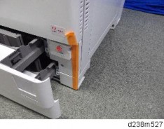
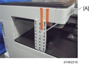
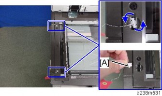
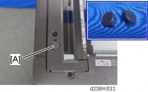
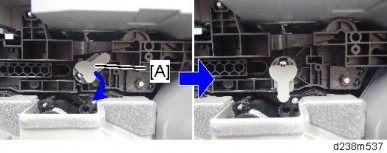
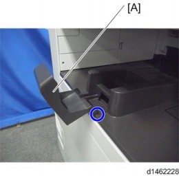
When attaching the reverse sensor, if you screw too tightly in the direction of the blue arrow, it may cause the gap between the guide plates [A] to be too narrow, resulting in paper jams. Make sure that there is a gap [A] of 3mm or more after you fasten the screw.

Replacement and Adjustment


Replacement and Adjustment
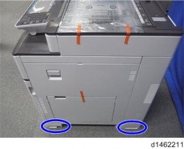
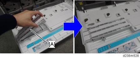
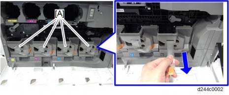
The 1st paper feed unit can be removed without removing the duplex unit (just open the right door), and you can remove the paper feed unit after pulling out the paper tray.
The 1st paper feed unit and 2nd paper feed unit are not interchangeable.


Replacement and Adjustment


Replacement and Adjustment


Replacement and Adjustment


Replacement and Adjustment


Replacement and Adjustment


Replacement and Adjustment


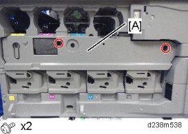
When attaching the bypass tray, pass the harness through the indicated position as shown.


Replacement and Adjustment


Replacement and Adjustment


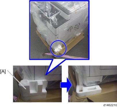

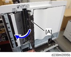
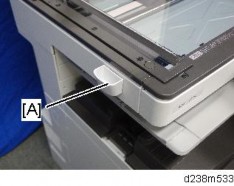
There is a hook in the tray cover. Be careful not to damage it during removal or installation.

Replacement and Adjustment
When installing, the holes must align as shown below.


Replacement and Adjustment
There is a hook in the tray cover. Be careful not to damage it during removal or installation.
Replacement and Adjustment

Replacement and Adjustment


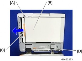
Make sure to release the tab on the right [C] first.
When you reattach this part, make sure to attach it from the tab on the left [B] first.

Replacement and Adjustment


Replacement and Adjustment
Before doing any work, touch a metal object to discharge static electricity from the body. There is a possibility that the electrical components may malfunction due to static electricity.
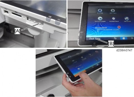
When disconnecting the FFC, release the lock.
[A]: Disconnect the scanner FFC for the IPU while pressing the lock release button.
[B]: Disconnect the other FFC while pressing the lock release levers on its sides.
[A] | IPU |
[B] | BCU |
[C] | Controller Box Cooling Fan |
[D] | Controller Board |
[E] | HDD |
Replacement and Adjustment
[A] | HVP_TTS |
[B] | Imaging IOB |

[A] | PSU (AC controller board) |
[B] | PSU (DC Power) |
[C] | PSU Cooling Fan |

[A] | HVP_CB |
[B] | Paper Transport IOB |
Replacement and Adjustment
The FFC connector has a lock mechanism. Do not use force to pull it out.
Disconnect the upper FFC (scanner) while pressing the lock release button. Disconnect the lower FFC while pressing the lock release levers on its sides.

The FFC connector has a lock mechanism. Do not use force to pull it out.
Disconnect the FFCs while pressing the lock release levers on its sides. Disconnecting the FFC without releasing the lock may cause the FFC or connector to be damaged, resulting in an SC670 error.

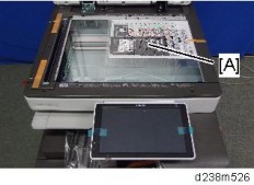
Remove the NVRAM (EEPROM) [A] from the old BCU. Then install it on the new BCU after you replace the BCU.
Replace the NVRAM (page 4-185) if the NVRAM on the old BCU is defective.
Make sure you print out the SMC reports ("SP Mode Data" and "Logging Data") before you replace the NVRAM (EEPROM).
Replacement and Adjustment
Keep NVRAMs (EEPROM) away from any objects that can cause static electricity. Static electricity can damage NVRAM data.
Make sure the serial number is input in the machine for the NVRAM data with SP5-811-004, if not, SC995-001 occurs
Make sure to shut down and reboot the machine once before printing/exporting the SMC. Otherwise, the latest settings may not be collected when the SMC is printed/exported.
When the power is turned ON, SC195-00 appears, but continue with the following steps.
For information on how to configure this SP, contact the supervisor in your branch office.
After changing the EEPROM, Some SPs do not have appropriate initial values. Because of this, steps 10 to 12 are done.
SP descriptions
Displays/Enters serial number of BCU EEPROM.
Displays machine serial number.
Sets the machine destination.
(1: Japan, 2: NA, 3: EU, 4: Taiwan, 5: Asia, 6: China, 7: Korea)
Clears non-volatile memory of engine.
Uploads the NVRAM data to an SD card.
Downloads data from an SD card to the NVRAM in the machine.
Keep NVRAMs away from any objects that can cause static electricity. Static electricity can damage NVRAM data.

Replacement and Adjustment
Make sure that the FRAM1 and FRAM2 are placed at the right position and orientation when attaching to the new board.
Incorrect installation of the NVRAM will damage both the controller board and NVRAM.

Position | Label on the board | Label on the NVRAM | |
[A] | Left | FRAM1 | 2M-1 |
[B] | Right | FRAM2 | 2M-2 |
When replacing the controller board, first, check which SDK applications have been installed. After replacing the controller board, re-install the SDK applications by following the installation instructions for each application.
After reinstalling the SDK applications, print the SMC (SP-5-990-024/025 (SMC: SDK/Application Info)). Then open the front upper cover. Store the SMC sheet and the SD card(s) that was used to install the SDK application(s).
Replacement and Adjustment
Referring to the following procedure, be sure that there are no mistakes in the mounting position and orientation of the NVRAMs.
Incorrect installation of the NVRAM will damage both the controller board and NVRAM.
SC195 (Machine serial number error) will be displayed if you forget to attach the NVRAM.
Passwords for the Supervisor and Administrator 1 will be discarded later in this procedure.
Installing a new NVRAM initializes SPs and issues an SC. Reset the SC with the procedure below.

Position | Label on the board | Label on the NVRAM | |
[A] | Left | FRAM1 | 2M-1 |
[B] | Right | FRAM2 | 2M-2 |
Make sure to shut down and reboot the machine once before printing/exporting the SMC.
Otherwise, the latest settings may not be collected when the SMC is printed/exported.
The address data stored in the machine will be discarded later during this procedure. So be sure to obtain a backup of the customer’s address book data.
Note that the counters for the user will be reset when doing the backup/restore of the address book data.
If they have a backup of the address book data, use their own backup data for restoring. This is because there is a risk that the data cannot be backed up properly depending on the NV-RAM condition.
Print the Box List with the User Tools/Counter.
[User Tools/Counter] - [Facsimile Features] - [General Settings] - [Box Setting: Print List]
Print the Special Sender List by pressing these buttons in the following order.
[User Tools/Counter] - [Facsimile Features] - [Reception Settings] - [Program Special Sender: Print List]
Write down the following fax settings.
[Receiver] in [User Tools/Counter] - [Facsimile Features] - [Reception Settings] - [Reception File Settings] - [Forwarding].
[Notify Destination] in [User Tools/Counter] - [Facsimile Features] - [Reception Settings] - [Reception File Settings] - [Store].
[Specify User] in [User Tools/Counter] - [Facsimile Features] - [Reception Settings] - [Stored Reception File User Setting].
[Notify Destination] in [User Tools/Counter] - [Facsimile Features] - [Reception Settings] - [Folder Transfer Result Report].
Specified folder in [User Tools/Counter] - [Facsimile Features] - [Send Settings] - [Backup File TX Setting].
[Receiver] in [User Tools/Counter] - [Facsimile Features] - [Reception Settings] - [Reception File Settings] - [Output Mode Switch Timer].
[Store: Notify Destination] in [User Tools/Counter] - [Facsimile Features] - [Reception Settings] - [Output Mode Switch Timer].
All the destination information shown on the display.
Replacement and Adjustment
In the fax settings, address book data is stored with entry IDs, which the system internally assigns to each data. The entry IDs may be changed due to
re-assigning in backup/restore operations.
Make sure that there is no transmission standby file. If any standby file exists, ask the customer to delete it or complete the transmission.
SC673 appears at start-up, but this is normal behavior. This is because the controller and the smart operation panel cannot communicate with each other due to changing the SP settings for the operation panel.
If you switch the screen to enter the SP mode, SC995-02 is displayed. However, continue the following steps.
SP5-748-101: (OpePanel Setting: Op Type Action Setting): Change bit 0 from 0 to 1.
SP5-748-201: (OpePanel Setting: Cheetah Panel Connect Setting): Change the value from 0 to 1.
SP5-752-001 (Copy FlairAPIFunction Setting): Change bit 0 from 0 to 1.
SP1-041-001 (Scan:FlairAPI Setting): Change bit 0 from 0 to 1.
SP3-301-001 (FAX:FlairAPI Setting) Change bit 0 from 0 to 1.
The model information is written on the NVRAM (Novita), so SC995-02 does not occur.
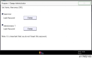
Program/Change Administrator will be displayed in Japanese, but this is normal.
The download will take a couple of minutes.
The screen "Program/Change Administrator" will be displayed in the language that is the same language as the time when the data was uploaded to the SD card in step 5.
After you execute this SP and exit SP mode, the Home screen is displayed and user functions can be used.
SP5-193-001 (External Controller Info. Settings) Change the value from 0 to 1.
SP5-895-001 (Application invalidation: Printer) Change the value from 0 to 1.
SP5-895-002 (Application invalidation: Scanner) Change the value from 0 to 1.
If you obtained the backup of the customer’s address book data in step 3, delete the backup immediately after the NV-RAM replacement to avoid accidentally taking out the customer’s data.
The counters will be reset.
Replacement and Adjustment
If you cannot execute SP5-824-001 or SP5-825-001 for some reason, try all the following things.
Check the changed SP value on the SMC which was output in step 2 and set it manually. Especially, ensure that the values of the following SPs are same as the setting before the replacement.
a. SP5-045-001 (Accounting counter: Counter Method)
b. SP5-302-002 (Set Time: Time Difference)
Because the PM counters have been reset during NV-RAM replacement, it is necessary to replace all the PM parts for proper PM management.
If a message tells you need a SD card to restore displays after the NV-RAM replacement, create a "SD card for restoration" and restore with the SD card.
SP descriptions
Uploads all directory information to the SD card.
Sets the operation panel type. 0: Normal operation panel
1: Smart operation panel
0: OFF
1: ON
Sets Copy FlairAPI Function enable / disable.
Sets Scanner FlairAPI Function enable / disable.
Sets Fax FlairAPI Function enable / disable.
Bit | Item | 0 | 1 | Description | Initial value |
0 | Flair API Server Boot | Disabled | Enabled | Specifies whether to start the HTTP server for Flair API. "0" disables all the Flair API functions (Remote UI). | 0 |
1 | Access Permission | Enabled | Disabled | Setting this value to “0” permits only internal access in the machine (MFP browser). Setting this value to “1” permits to access from external devices such as PC, Remote UI, IT-BOX. | 0 |
2 | Select IPv6/IPv4 | IPv6 | IPv4 | Setting this value to “0” permits only accessing with IPv6. Setting this value to “1” permits accessing with IPv4 or IPv6. | 0 |
3 | Remote UI | Not use | Use | Sets whether to use the Remote UI. | 0 |
4 | Reserved | - | - | N/A | N/A |
5 | Reserved | - | - | N/A | N/A |
6 | Reserved | - | - | N/A | N/A |
7 | Reserved | - | - | N/A | N/A |
The NIC and USB support features are built into the GW controller. Use this SP to enable and disable these features. In order to use the NIC and USB functions built into the controller board, these SP codes must be set to "1".
Uploads the NVRAM data to an SD card.
Downloads data from an SD card to the NVRAM in the machine.
Hides the input screen of the administrator password temporarily.
Replacement and Adjustment
Sets the model of the external controller connected to the main unit. 0: External Controller is not installed
1: EFI
2: Ratio
3: Egret
4: GJ
5: Creo
6: QX-100
7: Kurofune
8 to 10: Reserved
Downloads all directory information from the SD card.
Executes Process control.
Sets the counter methods as follows; Developments, Prints or Coverage.
Adjusts the RTC (real time clock) time setting for the local time zone. Examples: For Japan (+9 GMT), enter 540 (9 hours x 60 min.)
Japan: +540 (Tokyo) NA: -300 (New York) EU: + 60 (Paris) CHN: +480 (Beijing) TWN: +480 (Taipei)
AA: +480 (Hong Kong) KO: +540 (Korea)
Before replacing the HDD, copy the address book data to an SD card with SP5846-051 if possible.
If the customer is using the Data Overwrite Security, the Data Encryption feature or OCR Scanned PDF, these applications must be installed again.
Even if you use an HDD that is already formatted, it is recommended that you re-initialize.
SP descriptions
Initializes the hard disk.
Downloads the fixed stamp data from the machine ROM onto the hard disk. Then these stamps can be used by the User Tools menu. If this is not done, the user will not have access to the fixed stamps ("Confidential", "Secret", etc.).
You must always execute this SP after replacing the HDD or after formatting the HDD.
Downloads all directory information from the SD card.