
SERVICE MANUAL
![]()
It is the reader's responsibility when discussing the information contained within this document to maintain a level of confidentiality that is in the best interest of Ricoh USA, Inc. and its member companies.
NO PART OF THIS DOCUMENT MAY BE REPRODUCED IN ANY FASHION AND DISTRIBUTED WITHOUT THE PRIOR PERMISSION OF RICOH USA, Inc.
All product names, domain names or product illustrations, including desktop images, used in this document are trademarks, registered trademarks or the property of their respective companies.
They are used throughout this book in an informational or editorial fashion only and for the benefit of such companies. No such use, or the use of any trade name, or web site is intended to convey endorsement or other affiliation with Ricoh products.
2016 RICOH USA, Inc. All rights reserved.
WARNING
The Service Manual contains
regarding service techniques,
information procedures,
processes and spare parts of office equipment distributed by Ricoh USA, Inc. Users of this manual should be either service trained or certified by successfully completing a Ricoh Technical Training Program.
Untrained and uncertified users utilizing information contained in this service manual to repair or modify Ricoh equipment risk personal injury, damage to property or loss of warranty protection.
Ricoh USA, Inc.
PRODUCT CODE | COMPANY | ||
LANIER | RICOH | SAVIN | |
D243 | MP C2004 | MP C2004 | MP C2004 |
D244 | MP C2504 | MP C2504 | MP C2504 |
REV. NO. | DATE | COMMENTS |
* | 08/2016 | Original Printing |
TABLE OF CONTENTS
PRODUCT INFORMATION 1-1
PRODUCT OVERVIEW 1-1
COMPONENT LAYOUT 1-1
PAPER PATH 1-3
DRIVE LAYOUT 1-6
MACHINE CODES AND PERIPHERALS CONFIGURATION 1-8
MAIN MACHINE 1-8
-17............................................................................................................................1-8
-18............................................................................................................................1-9
-19............................................................................................................................1-9
-21............................................................................................................................1-9
-22............................................................................................................................1-9
-26..........................................................................................................................1-10
-27..........................................................................................................................1-10
-29..........................................................................................................................1-10
-65..........................................................................................................................1-10
OPTIONS 1-11
DIAGRAM 1-14
INSTALLATION 2-1
INSTALLATION REQUIREMENTS 2-1
ENVIRONMENT 2-1
MACHINE LEVEL 2-2
MACHINE SPACE REQUIREMENTS 2-2
MACHINE DIMENSIONS 2-3
Model -27, -29, -65 (220–240 V) 2-4
Model -17, -18 (120–127 V) 2-4
POWER REQUIREMENTS 2-5
Input Voltage Level 2-5
MAIN MACHINE INSTALLATION 2-6
IMPORTANT NOTICE ON SECURITY ISSUES 2-6
INSTALLATION FLOW CHART 2-8
ACCESSORY CHECK 2-8
INSTALLATION PROCEDURE 2-10
Removal of Packing Materials and Shipping Retainers 2-10
For Machines with preinstalled SPDF: Removal of protective sheet 2-16
Removal of PCDU Seals 2-16
Attaching the Optical Cloth Pocket 2-18
Attaching the Paper Exit Tray Parts 2-18
Checking the Position of the Paper Exit Feeler 2-19
Attaching the Decals 2-19
Toner Bottle Installation and Login Password Setting 2-20
For Machines with Preinstalled ARDF: Fax Stamp Installation (Option) 2-23
IMAGE QUALITY TEST/ SETTINGS 2-23
Before Test 2-23
Loading Paper 2-24
ACC Execution and Color Registration Adjustment 2-24
Checking the Copy Image with the Test Chart 2-27
Paper Settings 2-27
Auto Remote Firmware Update Settings 2-28
Enabling the Copy Data Security Function 2-34
HDD Security Function Setting 2-34
Settings Relevant to the Service Contract 2-34
MOVING THE MACHINE 2-36
Cautions upon Lashing 2-38
ANTI-CONDENSATION HEATER (SCANNER, PCDU) 2-39
ANTI-CONDENSATION HEATER (SCANNER) 2-39
Accessory Check 2-39
Installation Procedure 2-41
ANTI-CONDENSATION HEATER (PCDU) 2-50
Accessory Check 2-50
Installation Procedure 2-51
ANTI-CONDENSATION HEATER FOR PAPER FEED TRAYS 2-58
ACCESSORY CHECK 2-58
CONNECTING TO MAIN MACHINE TRAY 2-59
CONNECTING TO PAPER FEED UNIT PB3220/PB3210 2-62
CONNECTING TO PAPER FEED UNIT PB3150 2-65
2.5 PAPER FEED UNIT PB3220 (D787-18, -22)/ PB3210 (D787-17) 2-67
ACCESSORY CHECK 2-67
INSTALLATION PROCEDURE 2-67
PAPER FEED UNIT PB3150 (D694) 2-72
ACCESSORY CHECK 2-72
INSTALLATION PROCEDURE 2-72
CASTER TABLE TYPE M3 (D178) 2-76
ACCESSORY CHECK 2-76
INSTALLATION PROCEDURE 2-76
How to Place the MFP on the Caster Table 2-77
How to Place the Paper Feed Unit PB3150 on the Caster Table 2-78
PLATEN COVER PN2000 (D700) 2-79
ACCESSORY CHECK 2-79
INSTALLATION PROCEDURE 2-80
2.9 ARDF DF3090 (D779) 2-82
ACCESSORY CHECK 2-82
INSTALLATION PROCEDURE 2-82
When Feeding Thin Paper 2-86
2.10 SPDF DF3100 (D3B0) 2-87
ACCESSORY CHECK 2-87
INSTALLATION PROCEDURE 2-88
Attaching the SPDF 2-88
Adjust SP Settings 2-95
BIN TRAY BN3110 (D3CQ) 2-97
ACCESSORY CHECK 2-97
INSTALLATION PROCEDURE 2-98
Checking the Position of the Paper Exit Feeler 2-104
INTERNAL SHIFT TRAY SH3070 (D691) 2-105
ACCESSORY CHECK 2-105
INSTALLATION PROCEDURE 2-105
Checking the Position of the Paper Exit Feeler 2-108
SIDE TRAY TYPE M3 (D725) 2-110
ACCESSORY CHECK 2-110
INSTALLATION PROCEDURE 2-111
2.14 BRIDGE UNIT BU3070 (D685) 2-116
ACCESSORY CHECK 2-116
INSTALLATION PROCEDURE 2-116
BOOKLET FINISHER SR3220 (D3B9) 2-123
ACCESSORY CHECK 2-123
INSTALLATION PROCEDURE 2-124
Attaching the Proof Support Tray 2-130
PUNCH UNIT PU3050 2-132
ACCESSORY CHECK 2-132
INSTALLATION PROCEDURE 2-133
INTERNAL FINISHER SR3130 (D690) 2-144
ACCESSORY CHECK 2-144
INSTALLATION PROCEDURE 2-145
2.18 PUNCH UNIT PU3040 (D716) 2-156
ACCESSORY CHECK 2-156
INSTALLATION PROCEDURE 2-157
INTERNAL FINISHER SR3180 (D766) 2-163
ACCESSORY CHECK 2-163
INSTALLATION PROCEDURE 2-164
STAPLELESS STAPLER INITIAL SETTINGS 2-177
How to Change the Setting of Staple Method for Stapleless Stapler 2-177
How to set Margin Erase for Stapleless Stapler 2-178
BANNER PAPER GUIDE TRAY TYPE M19 (D3BF) 2-179
ACCESSORY CHECK 2-179
INSTALLATION PROCEDURE 2-179
IMAGEABLE AREA EXTENSION UNIT TYPE M19 (D3BR-07) 2-183
ACCESSORY CHECK 2-183
INSTALLATION PROCEDURE 2-183
When You Forgot to Change the SP 2-185
EXTERNAL KEYBOARD BRACKET TYPE M19 (D3BR-10) 2-187
ACCESSORY CHECK 2-187
INSTALLATION PROCEDURE 2-187
INTERNAL OPTIONS 2-192
LIST OF SLOTS 2-192
USB DEVICE SERVER OPTION TYPE M19 (D3BC-28,-29) 2-193
ACCESSORY CHECK 2-193
Interface Board Surface 2-193
INSTALLATION PROCEDURE 2-194
What Do the LED Indications Mean? 2-198
IP ADDRESS SETTING 2-199
EXTENDED USB BOARD TYPE M19 (D3BS-01) 2-201
ACCESSORY CHECK 2-201
INSTALLATION PROCEDURE 2-201
IEEE 1284 INTERFACE BOARD TYPE M19 (D3C0) 2-203
ACCESSORY CHECK 2-203
INSTALLATION PROCEDURE 2-203
IEEE 802.11AGN INTERFACE UNIT TYPE M19 (D3BR-01) 2-205
ACCESSORY CHECK 2-205
INSTALLATION PROCEDURE 2-206
Attaching the Boards 2-206
Attaching the Antenna 2-207
USER TOOL SETTINGS FOR IEEE 802.11A/G/N 2-208
SP MODE SETTINGS FOR IEEE 802.11 WIRELESS LAN 2-209
FILE FORMAT CONVERTER TYPE M19 (D3BR-04) 2-210
ACCESSORY CHECK 2-210
INSTALLATION PROCEDURE 2-211
BLUETOOTH INTERFACE UNIT TYPE D (D566-01) 2-212
ACCESSORY CHECK 2-212
INSTALLATION PROCEDURE 2-212
MEMORY UNIT TYPE M19 4GB (D3BX-03) 2-213
ACCESSORY CHECK 2-213
INSTALLATION PROCEDURE 2-213
ENHANCED SECURITY HDD OPTION TYPE M12 (D3A6-02) 2-215
ACCESSORY CHECK 2-215
INSTALLATION PROCEDURE 2-215
After Installing the HDD 2-218
OPTIONAL COUNTER INTERFACE UNIT TYPE M12 (B870-21) 2-220
ACCESSORY CHECK 2-220
INSTALLATION PROCEDURE 2-220
KEY COUNTER BRACKET TYPE M3 (D739-09) 2-223
ACCESSORY CHECK 2-223
INSTALLATION PROCEDURE 2-223
CARD READER BRACKET TYPE 3352 (D593-61) 2-228
ACCESSORY CHECK 2-228
INSTALLATION PROCEDURE 2-228
NFC CARD READER TYPE M19 (D3BS-21) 2-232
ACCESSORY CHECK 2-232
INSTALLATION PROCEDURE 2-233
SMART CARD READER BUILT-IN UNIT TYPE M19 (D3BS-22) 2-239
ACCESSORY CHECK 2-239
INSTALLATION PROCEDURE 2-239
Procedure for Connecting to the Main Machine USB Slot 2-239
Procedure for Connecting to the Operation Panel USB Slot 2-245
SD CARD OPTIONS 2-251
SD CARD SLOTS 2-251
LIST OF SLOTS USED 2-251
SD CARD APPLI MOVE 2-252
OVERVIEW 2-252
MOVE EXEC 2-253
UNDO EXEC 2-254
2.39 POSTSCRIPT3 UNIT TYPE M19 (D3BD-05, -06, -07) 2-256
ACCESSORY CHECK 2-256
INSTALLATION PROCEDURE 2-256
CAMERA DIRECT PRINT CARD TYPE M19 (D3BD-13) 2-258
ACCESSORY CHECK 2-258
INSTALLATION PROCEDURE 2-258
XPS DIRECT PRINT OPTION TYPE M19 (D3BC-24, -25, -26) 2-260
ACCESSORY CHECK 2-260
INSTALLATION PROCEDURE 2-260
2.42 OCR UNIT TYPE M13 (D3AC-23, -24, -25) 2-262
ACCESSORY CHECK 2-262
SEARCHABLE PDF FUNCTION OUTLINE 2-262
INSTALLATION PROCEDURE 2-262
RECOVERY PROCEDURE 2-264
DATAOVERWRITESECURITY UNIT TYPE M19 (D3BS-03) 2-265
OVERVIEW 2-265
ACCESSORY CHECK 2-265
BEFORE YOU BEGIN THE PROCEDURE 2-266
Seal Check and Removal 2-266
INSTALLATION PROCEDURE 2-267
CONFIGURING "AUTO ERASE MEMORY" (PERFORMED BY THE CUSTOMER) 2-269
@REMOTE SETTINGS 2-272
SECURITY SETTINGS 2-278
SECURITY FUNCTION INSTALLATION 2-278
DATA OVERWRITE SECURITY 2-279
Before You Begin the Procedure 2-279
Installation Procedure 2-279
Using Auto Erase Memory 2-280
HDD ENCRYPTION 2-282
Before You Begin the Procedure: 2-282
Installation Procedure: 2-282
Enable Encryption Setting 2-283
Check the Encryption Settings 2-285
Backing Up the Encryption Key 2-286
Encryption Key Restoration 2-287
PREVENTIVE MAINTENANCE 3-1
PM PARTS SETTINGS 3-1
REPLACEMENT PROCEDURE OF THE PM PARTS 3-1
Method 1: By SP3701 3-1
Method 2: By [PM Counter / New Unit Set] Menu 3-2
AFTER INSTALLING THE NEW PM PARTS 3-4
SP Descriptions 3-4
PREPARATION BEFORE OPERATION CHECK 3-5
SP Descriptions 3-5
OPERATION CHECK 3-5
REPLACEMENT AND ADJUSTMENT 4-1
NOTES ON THE MAIN POWER SWITCH 4-1
PUSH SWITCH 4-1
Characteristics of the Push Switch (DC Switch) 4-1
Shutdown Method 4-2
Forced Shutdown 4-3
BEFOREHAND 4-3
SPECIAL TOOLS 4-4
EXTERIOR COVERS 4-5
OVERVIEW 4-6
Front and Rear Side Covers 4-6
Right and Left Side Covers 4-7
Paper Exit Covers 4-8
Inner Covers 4-8
FRONT COVER 4-9
CONTROLLER COVER 4-10
UPPER LEFT COVER 4-10
LEFT REAR COVER 4-11
LEFT COVER 4-12
REAR COVER 4-14
REAR LOWER COVER 4-15
RIGHT REAR COVER 4-16
RIGHT UPPER COVER 4-17
FRONT UPPER COVER 4-17
PROXIMITY SENSOR (HUMAN DETECTION SENSOR) 4-18
MAIN POWER SWITCH COVER 4-19
WASTE TONER COVER 4-20
INVERTER TRAY 4-20
PAPER EXIT TRAY 4-21
PAPER EXIT COVER 4-21
PAPER EXIT LOWER COVER 4-22
PAPER EXIT FRONT COVER 4-23
INNER UPPER COVER 4-23
INNER LOWER COVER 4-24
SMART OPERATION PANEL 4-25
OPERATION PANEL UNIT 4-25
USB CABLE 4-28
4.6 ADF 4-30
4.6.1 ADF REMOVAL 4-30
SCANNER UNIT 4-33
BEFORE YOU BEGIN 4-33
SCANNER EXTERIOR 4-33
Scanner Front Cover 4-33
Scanner Right Cover 4-34
Scanner Left Cover 4-35
Scanner Upper Cover 4-35
EXPOSURE GLASS 4-36
SCANNER CARRIAGE 4-37
Cleaning the Scanner Carriage Mirror 4-41
SCANNER MOTOR 4-43
APS SENSOR 4-44
SCANNER HP SENSOR 4-45
ARDF/PLATEN COVER SENSOR 4-46
SCANNER FFC 4-46
When Changing the FFC 4-47
LASER UNIT 4-50
LASER UNIT 4-50
Before Replacement 4-50
Removing 4-52
Installing a New Laser Unit 4-52
Adjustment after Replacing the Laser Unit 4-53
POLYGON MIRROR MOTOR 4-55
Adjustment after Replacing the Polygon Mirror Motor 4-55
SP DESCRIPTIONS 4-56
4.9 PCDU 4-58
4.9.1 PCDU 4-58
Adjustment after Replacing the PCDU 4-60
PCU/DEVELOPMENT UNIT 4-61
Before Replacing a PCU 4-61
Before Replacing a Development Unit 4-63
Replacement 4-63
Notes for Assembling PCU/Development Unit 4-66
Method for Checking after Replacement 4-66
Adjustment after Replacing the PCU and/or the Development Unit 4-67
IMAGING TEMPERATURE SENSOR (THERMISTOR) 4-67
WASTE TONER 4-69
4.10.1 WASTE TONER BOTTLE 4-69
Before Replacing the Waste Toner Bottle 4-69
Replacement 4-69
IMAGE TRANSFER UNIT 4-71
IMAGE TRANSFER BELT UNIT 4-71
What to Do before Replacing the Image Transfer Belt 4-72
Replacement 4-72
IMAGE TRANSFER CLEANING UNIT 4-75
What to Do before Replacing the Image Transfer Cleaning Unit 4-76
Replacement 4-76
IMAGE TRANSFER BELT 4-78
Attaching the Belt 4-81
Adjustment after replacing the Image transfer belt 4-85
PAPER TRANSFER ROLLER 4-86
When reinstalling the paper transfer roller 4-87
PAPER TRANSFER ROLLER UNIT 4-89
What to Do before Replacing the Paper Transfer Roller Unit 4-89
Replacement 4-89
FUSING ENTRANCE SENSOR 4-91
TM/ID SENSOR 4-92
Before Replacing the TM/ID sensor 4-92
Replacement procedure 4-93
Adjustment after Replacing the TM/ID sensor 4-95
TEMPERATURE AND HUMIDITY SENSOR 4-97
ITB CONTACT AND RELEASE SENSOR 4-98
IMAGE TRANSFER LOCK UNIT 4-99
Installing the Image Transfer Lock Unit 4-100
DRIVE UNIT 4-102
OVERVIEW 4-102
PAPER FEED MOTOR 4-103
TRANSPORT MOTOR 4-103
PAPER TRANSFER CONTACT AND RELEASE MOTOR UNIT 4-104
IMAGING DRIVE UNIT 4-104
PCU MOTOR: CMY 4-106
DEVELOPMENT MOTOR: CMY 4-107
DEVELOPMENT SOLENOID 4-108
PCU MOTOR: BLACK / ITB DRIVE MOTOR 4-109
REGISTRATION MOTOR 4-110
FUSING MOTOR 4-111
PAPER EXIT/ PRESSURE RELEASE MOTOR 4-111
DUPLEX ENTRANCE MOTOR 4-112
TONER SUPPLY MOTOR 4-113
SUB HOPPER 4-114
K 4-115
C 4-116
M 4-117
Y 4-118
TONER END SENSOR 4-119
TONER BOTTLE DRIVE MOTOR 4-120
K 4-120
C 4-120
M 4-121
Y 4-121
ID CHIP CONTACT BOARD 4-122
K 4-122
C 4-122
M 4-122
Y 4-123
TRANSPORT COIL UNIT 4-124
Y 4-124
M 4-127
C 4-128
K 4-128
FUSING UNIT 4-129
FUSING UNIT 4-129
FUSING ENTRANCE GUIDE PLATE 4-130
Cleaning the Fusing Entrance Guide Plate 4-131
FUSING EXIT GUIDE PLATE 4-131
Cleaning the Fusing Exit Guide Plate 4-132
FUSING UPPER COVER 4-132
FUSING LOWER COVER 4-133
FUSING SLEEVE BELT UNIT 4-134
Adjustment before Replacing the Fusing Sleeve Belt Unit 4-134
Replacement 4-134
PRESSURE ROLLER 4-137
Adjustment before Replacing the Pressure Roller 4-137
Replacement 4-138
FUSING SLEEVE THERMOSTAT UNIT 4-140
NON-CONTACT THERMISTOR 4-141
PRESSURE ROLLER THERMISTOR 4-142
THERMOPILE UNIT 4-142
PRESSURE ROLLER HP SENSOR 4-143
FUSING EXIT DRIVE SOLENOID 4-144
PAPER EXIT 4-145
PAPER EXIT UNIT 4-145
PAPER EXIT SOLENOID 4-146
PAPER EXIT SENSOR 4-146
REVERSE SENSOR 4-148
REVERSE MOTOR 4-149
FUSING EXIT SENSOR 4-150
PAPER FEED 4-151
PAPER FEED UNIT 4-151
1st Paper Feed Unit 4-151
2nd Paper Feed Unit 4-152
PAPER DUST COLLECTION UNIT 4-155
PICK-UP ROLLER, PAPER FEED ROLLER, SEPARATION ROLLER, TORQUE LIMITER 4-156
1ST TRAY LIFT MOTOR/ 2ND TRAY LIFT MOTOR 4-158
TRANSPORT SENSOR 4-159
UPPER LIMIT SENSOR 4-160
PAPER END SENSOR 4-160
REGISTRATION SENSOR 4-161
BYPASS TRAY UNIT 4-162
BYPASS TRAY 4-162
BYPASS PAPER END SENSOR 4-164
BYPASS PICK-UP ROLLER 4-165
BYPASS PAPER FEED ROLLER 4-166
BYPASS SEPARATION ROLLER/TORQUE LIMITER 4-166
BYPASS WIDTH SENSOR 4-168
BYPASS LENGTH SENSOR 4-170
DUPLEX UNIT 4-173
DUPLEX UNIT 4-173
DUPLEX/BYPASS MOTOR 4-175
DUPLEX ENTRANCE SENSOR 4-176
DUPLEX EXIT SENSOR 4-177
ELECTRICAL COMPONENTS 4-179
OVERVIEW 4-180
Printed Circuits/Parts inside the Controller Box 4-180
Printed Circuits behind the Controller Box 4-181
Printed Circuit/Parts inside the Power Box 4-181
Printed Circuits behind the Power Box 4-182
CONTROLLER BOX COVER 4-182
4.18.3 IPU 4-183
4.18.4 BCU 4-184
When installing the new BCU 4-184
Replacing the NVRAM (EEPROM) on the BCU 4-185
4.18.5 CONTROLLER BOARD 4-186
Replacing the NVRAMs on the Controller Board 4-189
4.18.6 HDD 4-196
Adjustment after replacement 4-196
CONTROLLER BOX 4-197
IMAGING IOB 4-198
4.18.9 HVP_TTS 4-200
PSU (AC CONTROLLER BOARD) 4-201
PSU (DC POWER) 4-202
POWER SUPPLY BOX 4-203
PAPER TRANSPORT IOB 4-204
4.18.14 HVP-CB 4-204
HVP-CB with Bracket 4-204
4.18.15 PROXIMITY SENSOR (HUMAN DETECTION SENSOR) BOARD 4-206
FANS/FILTERS 4-207
OZONE FILTER/DUST FILTER 4-207
Adjustment before Replacing the Dust Filter 4-207
Replacement 4-207
DEODORIZATION FILTER 4-208
DEVELOPMENT INTAKE FAN 4-209
OZONE EXHAUST FAN 4-210
PAPER EXIT COOLING FAN 4-210
FUSING EXHAUST FAN 4-211
TONER SUPPLY COOLING FAN 4-212
PSU COOLING FAN 4-213
CONTROLLER BOX COOLING FAN 4-213
IMAGE ADJUSTMENT 4-214
AUTO COLOR CALIBRATION 4-214
SCANNING 4-216
Scanner Sub-scan Magnification 4-216
Scanner Leading Edge and Side-to-side Registration 4-216
4.20.3 ARDF 4-217
ARDF Side-to-side, Leading Edge Registration and Trailing Edge 4-217
ARDF Sub-scan Magnification 4-218
REGISTRATION 4-218
Image Area 4-218
Leading Edge 4-218
Side to Side 4-218
Adjustment Standard 4-218
Paper Registration Standard 4-218
Adjustment Procedure 4-219
ERASE MARGIN ADJUSTMENT 4-219
ADJUSTING THE TONE OF THE PRINTED IMAGE 4-220
ADJUSTMENT BY CHANGING THE PRINTER DRIVER SETTING 4-221
Opening the Printer Driver's "Color Balance Details" Window 4-221
Color Balance Details Window 4-223
Adjusting the Tone in the "Color Balance Details" Window 4-224
Adjustment Examples 4-226
ADJUSTMENT BY CHANGING THE MACHINE’S PROFILE SETTING 4-228
Procedure to Change the Profile Setting 4-228
Patterns and Tendency of the Tone for Each Profile 4-229
PRINTER GAMMA CORRECTION 4-230
COLOR REGISTRATION 4-233
Check the Occurrence of Color Registration Errors 4-233
Judgment for Type of Color Registration Error 4-233
SYSTEM MAINTENANCE 5-1
SERVICE PROGRAM MODE 5-1
ENTERING SP MODE 5-1
EXITING SP MODE 5-2
TYPES OF SP MODES 5-2
SP Mode Button Summary 5-3
Switching Between SP Mode and Copy Mode for Test Printing 5-4
Selecting the Program Number 5-4
Service Mode Lock/Unlock 5-5
REMARKS 5-5
Others 5-6
SP TABLES 5-8
FIRMWARE UPDATE (SD CARD) 5-9
OVERVIEW 5-9
FIRMWARE TYPE 5-9
PROCEDURE 5-12
Preparation 5-12
Update procedure 5-12
ERROR SCREENS DURING UPDATING 5-16
FIRMWARE UPDATE (REMOTE FIRMWARE UPDATE) 5-22
RFU PERFORMABLE CONDITION 5-22
FIRMWARE UPDATE (SMART FIRMWARE UPDATE) 5-23
OVERVIEW 5-23
IMMEDIATE UPDATE 5-24
UPDATE AT THE NEXT VISIT (RESERVE) 5-27
How to Set the Machine to Download Firmware Later (Reserve) 5-27
How to Check if the Firmware Downloaded with Reserve 5-29
How to Install Firmware Downloaded with Reserve 5-31
UPDATE VIA SD CARD 5-34
FIRMWARE UPDATE (AUTO REMOTE FIRMWARE UPDATE) 5-36
OVERVIEW 5-36
DOWNLOADING AND UPDATING PROCESS 5-37
Downloads the latest package 5-37
Judgement of ARFU 5-38
Update Process 5-40
Checking the ARFU Result 5-43
Checking the Result Using the Logging Data 5-43
RELATED SP 5-43
UPDATING JAVAVM 5-49
CREATING AN SD CARD FOR UPDATING 5-49
Updating Procedure 5-49
List of Error Messages 5-50
NVRAM DATA UPLOAD/DOWNLOAD 5-52
UPLOADING CONTENT OF NVRAM TO AN SD CARD 5-52
DOWNLOADING AN SD CARD TO NVRAM 5-53
ADDRESS BOOK UPLOAD/DOWNLOAD 5-54
INFORMATION LIST 5-54
DOWNLOAD 5-54
UPLOAD 5-55
CAPTURING THE DEVICE LOGS 5-56
OVERVIEW 5-56
Security of the Operation Log 5-58
RETRIEVING THE DEVICE LOGS VIA OPERATION PANEL 5-58
Procedure for Retrieving the Device Log with SD Card 5-59
RETRIEVING THE DEVICE LOGS VIA WEB IMAGE MONITOR 5-62
SMC LIST CARD SAVE FUNCTION 5-65
OVERVIEW 5-65
SMC List Card Save 5-65
PROCEDURE 5-65
FILE NAMES OF THE SAVED SMC LISTS 5-68
ERROR MESSAGES 5-68
UP/SP DATA IMPORT/EXPORT 5-69
UP DATA IMPORT/EXPORT 5-69
Data that can be imported and exported 5-69
Data that cannot be imported or exported 5-69
Exporting Device Information 5-70
Importing Device Information 5-71
SP DATA IMPORT/EXPORT 5-71
Data that can be imported and exported 5-71
Exporting Device Information 5-72
Importing Device Information 5-74
POSSIBLE SOLUTIONS FOR IMPORT/EXPORT PROBLEMS 5-75
CARD SAVE FUNCTION 5-78
OVERVIEW 5-78
Card Save: 5-78
PROCEDURE 5-78
ERROR MESSAGES 5-81
TROUBLESHOOTING 6-1
SELF-DIAGNOSTIC MODE 6-1
SC AUTOMATIC REBOOT 6-1
CONTROLLER SELF-DIAGNOSIS OUTLINE 6-3
CONTROLLER SELF-DIAGNOSIS FLOWCHART 6-4
HDD-RELATED MESSAGE 6-7
SERVICE CALL CONDITIONS 6-9
SUMMARY 6-9
SC Logging 6-10
LIST OF AUTOMATIC REBOOT TARGET SC 6-10
Engine SC 6-10
Controller SC 6-19
SC CODE CLASSIFICATION 6-22
6.3 SERVICE CALL 101-195 6-23
6.3.1 SC100 (ENGINE: SCANNING) 6-23
6.4 SERVICE CALL 202-285 6-37
6.4.1 SC200 (ENGINE: IMAGE WRITING) 6-37
6.5 SERVICE CALL 312-396 6-46
6.5.1 SC300 (ENGINE: CHARGE, DEVELOPMENT) 6-46
6.6 SERVICE CALL 441-498 6-55
6.6.1 SC400 (ENGINE: AROUND THE DRUM) 6-55
6.7 SERVICE CALL 501-584 6-60
SC500 (ENGINE: PAPER TRANSPORT 1: PAPER FEED, DUPLEX, TRANSPORT) 6-60
SC500 (ENGINE: FUSING) 6-72
Fusing Sleeve (Center) Error (SC54*-**) 6-76
Fusing Sleeve (Edge) Error (SC55*-**) 6-84
Pressure Roller Thermistor (Center) Error (SC56*-**) 6-93
Pressure Roller Thermistor (Edge) Error (SC57*-**) 6-98
Pressure Roller Thermistor (Full-bleed edge) Error (SC58*-**) 6-102
6.8 SERVICE CALL 620-687 6-106
SC600 (ENGINE: COMMUNICATION AND OTHERS) 6-106
SC600 (CONTROLLER) 6-129
6.9 SERVICE CALL 700-792 6-142
6.9.1 SC700 (ENGINE: PERIPHERALS) 6-142
6.10 SERVICE CALL 816-899 6-169
6.10.1 SC800 (CONTROLLER) 6-169
6.11SERVICE CALL 900-998 6-210
SC900 (ENGINE: OTHERS) 6-210
SC900 (CONTROLLER) 6-212
TROUBLESHOOTING FOR SC ERRORS 6-219
WHEN SC285-02 (MUSIC ERROR) IS DISPLAYED 6-219
Causes 6-219
Solutions 6-220
WHEN SC370 (TM (ID) SENSOR CALIBRATION ERROR) IS DISPLAYED.6-222 Causes 6-222
Solutions 6-222
Recovery Check Procedure 6-222
Adjustment after Recovery 6-223
WHEN SC501, SC502, SC503, OR SC504 (PAPER TRAY ERROR) IS DISPLAYED 6-224
Solutions 6-224
WHEN SC544-02, SC554-02 (NON-CONTACT THERMISTOR HIGH TEMPERATURE DETECTION) IS DISPLAYED 6-224
How to Clear SC544-02/SC554-02 with a New Unit Detection Fuse 6-226
6.12.5 ISOLATION DIAGRAM OF SC663, 664, 665, 667, 668, AND 670-01 6-227
WHEN SC670 (ENGINE START UP ERROR) IS DISPLAYED 6-227
Causes 6-227
Solutions 6-227
WHEN SC672 (CONTROLLER START UP ERROR) IS DISPLAYED 6-229
Symptom 6-229
Causes 6-229
Solutions 6-230
[A]: LEDs on the controller board 6-233
[B]: Abnormal mode: LEDs on the controller board 6-234
[C]: Reconnecting and replacing the USB cable 6-234
[D]: Replacing the Memory 6-236
[E]: CMOS clear 6-236
[F]: Fuse on the IPU 6-237
[G]: Replacing the USB cable and the operation panel 6-237
WHEN ABNORMAL NOISE OCCURS 6-243
PROCEDURE OF CHECKING ABNORMAL NOISE OF DRIVE UNIT (PERIPHERAL FUSING) 6-243
OPERATION CHECK PROCEDURES OF THE TONER SUPPLY MOTOR/TONER BOTTLE DRIVE MOTOR 6-246
JAM DETECTION 6-247
JAM DISPLAY 6-247
CLEARING A PAPER JAM 6-247
PAPER JAM HISTORY 6-248
History Checking Method 6-248
Paper Jam Display 6-248
JAM CODES AND DISPLAY CODES 6-248
PAPER SIZE CODE 6-256
SENSOR LOCATIONS 6-257
TROUBLESHOOTING FOR TRANSPORT/PAPER FEEDING OF THE MACHINE 6-258
CURLED PAPER 6-258
INITIAL JAM 6-258
Initial Jam: Cause Code 001 / Location Code A 6-258
Initial Jam: Cause Code 001 / Location Code B 6-259
Initial Jam: Cause Code 001 / Location Code C 6-260
Initial Jam: Cause Code 001 / Location Code Z 6-261
6.15.3 JAM 6-262
Bypass No Feeding: Cause Code 008 6-262
Tray 1 Transport Sensor: Late Jam : Cause Code 011 6-263
Tray 2 Transport Sensor : Late Jam : Cause Code 012 6-265
Registration Sensor : Late Jam : Cause Code 017 6-266
Fusing Entrance Sensor : Late Jam : Cause Code 018 6-266
Fusing Exit Sensor : Late Jam : Cause Code 019 6-268
Paper Exit Sensor : Late Jam : Cause Code 020 6-269
Tray 1 Transport Sensor : Lag Jam : Cause Code 051 6-270
Tray 2 Transport Sensor: Lag Jam: Cause Code 052 6-273
Registration Sensor: Lag Jam: Cause Code 057 6-275
Paper Exit Sensor: Lag Jam: Cause Code 060 6-276
Reverse Sensor: Late Jam: Cause Code 024 6-277
Reverse Sensor: Lag Jam : Cause Code 064 6-279
Duplex Exit Sensor: Late Jam: Cause Code 025 6-280
Duplex Exit Sensor: Lag Jam: Cause Code 065 6-281
Duplex Entrance Sensor: Late Jam: Cause Code 027 6-282
Duplex Entrance Sensor: Lag Jam: Cause Code 067 6-284
Duplex No Feeding: Cause Code 009 6-286
Bypass Transport Sensor 1: Lag Jam: Cause Code 048 6-287
DISPLAY ERROR 6-288
"No paper in Tray 1" is displayed even when the paper is in 6-288
"No paper in Tray 2" is displayed even when the paper is in 6-288
"Tray 1 not set" is displayed even when the tray is set 6-289
"Tray 2 not set" is displayed even when the tray is set 6-290
Wrong paper size displayed on the operation panel 6-290
Does not shift to right door open status 6-291
OTHERS 6-292
"Replace the waste toner bottle" is displayed even when it is clear that the waste toner bottle is not full 6-292
Waste toner bottle is never full 6-293
No waste toner bottle set is displayed on controller board even when it is clear that is set 6-293
Waste toner bottle is not detected even when it is set 6-293
Paper transfer unit open/close LED not lit and paper transfer unit open 6-294
Paper transfer unit open/close LED not lit 6-294
Paper transfer unit open/close LED always lit 6-295
TROUBLESHOOTING FOR FINISHING OPTIONS 6-296
FINISHER REGISTRATION ADJUSTMENT FOR BOOKLET FINISHER SR3220 (D3B9) 6-296
FINISHER JOGGER PROBLEM (FOR BOOKLET FINISHER SR3220 (D3B9) 6-298
EARLY TRAY FULL DETECTION MYLAR FOR INTERNAL FINISHER SR3130 (D690) 6-299
Pasting the Mylar 6-299
PAPER CURL PROBLEM FOR SR3180 (D766) 6-302
MAXIMUM NUMBER OF SHEETS FOR STAPLING AND WHAT HAPPENS WHEN THE JOB HAS TOO MANY PAGES 6-304
Specifications: Maximum sheet capability for staple jobs 6-304
Behavior: When the number of sheets exceeds the maximum staple capability6-304 Select the behavior when the job has more than the maximum of staple capability with SP5199 6-305
ELECTRICAL COMPONENT DEFECTS 6-306
6.17.1 FUSES 6-306
VERTICAL STREAKS ON COPIES DUE TO SCANNING PROBLEMS 6-309
OVERVIEW 6-309
Converting the ARDF DF3090 to Contact Scanning 6-310
Converting the SPDF3100 to Contact Scanning 6-312
IMAGE QUALITY PROBLEMS 6-315
MISJUDGMENT FOR AUTO COLOR SELECTION (COPY/SCANNER) 6-315
Error Condition 6-315
Causes 6-315
Solutions 6-316
MISJUDGMENT FOR AUTO COLOR SELECTION (E.G. WHEN USING PAPER WHICH HAS A STRONG BLUE COMPONENT) 6-317
WHEN AN ABNORMAL IMAGE IS GENERATED 6-318
OTHER TROUBLESHOOTING 6-320
WHEN FLUORESCENT/ LED LAMPS FLICKER 6-320
DETAILED DESCRIPTIONS 7-1
GUIDANCE FOR THOSE WHO ARE FAMILIAR WITH PREDECESSOR PRODUCTS7-1 7.1.1 CHANGES FROM THE PREVIOUS MACHINE 7-1
Scanner 7-1
Image Processing 7-2
Process Control 7-2
Laser Exposure 7-3
PCDU (Photo Conductor and Development Unit) 7-3
Waste Toner 7-4
Image Transfer and Paper Transfer 7-4
Feed / Transport Part 7-5
Fusing 7-6
Electrical Parts 7-7
Exterior Cover / Air Flows (Fan Control) 7-7
Drive Parts 7-8
Others 7-9
COMPONENT LAYOUT 7-10
SCANNER UNIT 7-10
LASER EXPOSURE UNIT 7-11
IMAGE TRANSFER UNIT 7-12
7.2.4 PCDU 7-13
TONER SUPPLY / WASTE TONER BOTTLE 7-14
PAPER FEED UNIT 7-15
DUPLEX UNIT 7-16
BYPASS UNIT 7-17
FUSING UNIT 7-18
PAPER TRANSFER / PAPER EXIT 7-19
AIR FLOW 7-20
DRIVE UNIT 7-21
BOARD / SWITCH 7-22
SCANNING 7-23
OVERVIEW 7-23
Reading System 7-24
Scanner 7-24
MECHANISM 7-25
Scanner Drive 7-25
Operation Flowchart 7-26
Scanner Carriage Storage Control 7-26
Document Size Detection 7-27
Improved Tolerance to Black Lines When Paper Passes through ARDF/SPDF ..7-30 Difference between Non-contact Transport and Contact Transport in DF Scanning
...............................................................................................................................7-32
Anti-Condensation Heater 7-34
IMAGE PROCESSING 7-35
MECHANISM 7-35
SBU 7-35
IPU 7-36
LASER EXPOSURE 7-38
OVERVIEW 7-38
Parts Construction 7-39
MECHANISM 7-41
LD Drive Board 7-41
LD Safety Switch 7-41
Circuit Diagram 7-41
Line Scanning Mechanism 7-42
PROCESS CONTROL 7-43
MECHANISM 7-43
Sensor Construction 7-43
Outline of the ID Sensors 7-43
Outline of the TD sensor 7-44
PROCESS CONTROL 7-44
Outline 7-44
Result Code for Executing Process Control 7-45
The Process Control Procedure 7-47
Electrified Potential / Development Bias, Vref Correction 7-48
LD Power Control 7-49
Toner Supply Control 7-50
Developer Initial Setting 7-50
MUSIC (AUTOMATIC COLOR REGISTRATION CORRECTION) 7-51
Correction Timing 7-51
Executing MUSIC Manually 7-52
[Color Registration] in User Tools (SP2-111-004) 7-52
MUSIC Error Judgment 7-53
REAL TIME PROCESS CONTROL 7-54
IBACC 7-55
Outline 7-55
Operation Timing 7-55
Patch Pattern 7-55
SP Descriptions 7-56
PCDU (PHOTO CONDUCTOR AND DEVELOPMENT UNIT) 7-59
OVERVIEW 7-59
MECHANISM (PCU) 7-60
Drum Drive 7-60
Charge 7-60
Drum Cleaning 7-60
MECHANISM (DEVELOPMENT) 7-61
Development System 7-61
Agitation System 7-61
TD Sensor 7-62
Pressure Release Filter 7-62
Development Drive 7-62
Development Bias 7-62
TONER SUPPLY 7-63
OVERVIEW 7-63
MECHANISM 7-63
Toner Supply (Toner Cartridge - Sub-hopper) 7-63
Toner Bottle ID Chip 7-65
Toner Supply (Sub-hopper - Development Unit) 7-65
Drive 7-66
Toner Near End/ Toner End Detection 7-66
SP Descriptions 7-69
WASTE TONER 7-71
OVERVIEW 7-71
MECHANISM 7-71
Waste Toner Bottle Set Detection 7-71
Waste Toner Drive 7-71
Waste Toner Recovery Path (PCU/Image Transfer Unit) 7-71
Waste Toner Bottle Full Detection 7-72
Waste Toner Cover 7-73
IMAGE TRANSFER AND PAPER TRANSFER 7-74
OVERVIEW 7-74
Image Transfer Unit 7-74
Paper Transfer Unit 7-75
IMAGE TRANSFER UNIT MECHANISM 7-76
Drive Mechanism 7-76
Transfer Bias 7-76
ITB Contact and Release 7-77
Image Transfer Belt Drive Control 7-77
Image Transfer Flow 7-77
IMAGE TRANSFER BELT CLEANING MECHANISM 7-78
PAPER TRANSFER UNIT MECHANISM 7-78
Paper Transfer Mechanism 7-78
PTR (Paper Transfer Roller) Drive 7-78
PTR (Paper Transfer Roller) Contact and Separation 7-78
Separation 7-79
TM/ID Sensor 7-80
PAPER FEED/ TRANSPORT SECTION 7-81
OVERVIEW 7-81
PAPER FEED/ TRANSPORT PART 7-82
Tray Base Plate Lift 7-82
Paper Feed Mechanism 7-85
Paper Feed Transport Mechanism 7-87
Paper Size Detection (1st Paper Supply Tray) 7-87
Paper Size Detection (2nd Paper Supply Tray) 7-87
Remaining Paper Detection 7-89
Paper End Detection 7-90
Paper Supply Drive 7-91
Paper Dust Removal Mechanism 7-93
BYPASS FEED SECTION 7-94
Bypass Feed Paper/ Separation Mechanism 7-94
Bypass Feed Paper Size Detection 7-95
Bypass Feed Paper End Detection 7-95
Bypass Paper Feeder Drive 7-95
DUPLEX SECTION 7-96
Transport Inversion Mechanism 7-97
Duplex Drive 7-97
Interleave Mechanism 7-98
PAPER EXIT UNIT 7-99
Delivery Location Change-over 7-99
Paper Exit Full/ Paper Exit Jam Detection 7-101
DRIVE/SENSOR LAYOUT 7-102
Transport Roller Drive Source 7-102
Gate/Pick-up Arm Drive Source 7-104
Inter-Roller Transport Path 7-105
Sensor Position 7-106
Paper Exit Driven Roller and Paper Support Guide 7-106
Removing Wrinkling in the Tray 7-107
FUSING 7-109
OVERVIEW 7-109
MECHANISM 7-111
Fusing System 7-111
Fusing Drive 7-112
Pressure Release Mechanism 7-113
Fusing Temperature Control 7-114
CPM Down Control 7-115
Curl Correction Mechanism 7-117
ELECTRICAL PARTS 7-121
BLOCK DIAGRAM 7-121
BOARD OUTLINE 7-121
Controller 7-121
SBU 7-121
LDB 7-121
BCU 7-121
IPU 7-122
MSENS1 (Proximity Sensor (Human Detection Sensor), MSENS2 (Proximity Sensor (Human Detection Sensor) Board) 7-122
IOB 7-122
FCU 7-122
OPU 7-122
HVP (Composite High-Voltage Power Supply TTS/CB) 7-122
PSU 7-122
ANTI-CONDENSATION HEATER FOR SCANNER, PCDU, AND PAPER FEED TRAY 7-123
Circuit Configuration 7-123
EXTERIOR COVER/ AIR FLOWS (FAN CONTROL) 7-124
OVERVIEW 7-124
MECHANISM 7-126
Cooling of PSU 7-126
Cooling of Toner Supply Parts 7-126
Cooling of PCDU parts 7-126
Cooling of Fusing Parts 7-126
Cooling in Controller Box 7-126
Crisis Management When Temperature Rises in the Machine 7-126
Helmholtz Silencer 7-128
ENERGY SAVE 7-129
ENERGY SAVER MODES 7-129
Setting Items that are Related to Energy Saving 7-129
Recovery Time/ Reduced Electrical Consumption 7-131
POWER STATES OF THIS MACHINE 7-132
Device state for each Energy Saving state 7-134
VERIFICATION OF UP TIME FOR EACH ENERGY SAVING STATE 7-136
CHECKING THE UP TIME BY DEVICE STATE 7-137
RECOMMENDATION 7-138
PROXIMITY SENSOR (HUMAN DETECTION SENSOR) 7-139
OVERVIEW 7-139
SENSOR OPERATION 7-140
OPERATION MODES 7-140
USER TOOL 7-141
RELATED SC CODES 7-141
RELATED SP CODE 7-141
READ THIS FIRST
Symbols, Abbreviations and Trademarks
Symbols, Abbreviations
This manual uses several symbols and abbreviations. The meaning of those symbols and abbreviations are as follows:
Symbol | What it means |
| Clip ring |
| Screw |
| Connector |
| Clamp |
| E-ring |
| Flat flexible cable |
| Timing belt |
SEF | Short edge feed [A] |
LEF | Long edge feed [B] |
K | Black |
C | Cyan |
M | Magenta |
Y | Yellow |
B/W, BW | Black and white |
FC | Full color |
Trademarks
Adobe, Acrobat, PageMaker, PostScript, and PostScript 3 are either registered trademarks or trademarks of Adobe Systems Incorporated in the United States and/or other countries.
The Bluetooth® word mark and logos are registered trademarks owned by Bluetooth SIG, Inc. and any use of such marks by Ricoh Company, Ltd. is under license.
Firefox and Thunderbird are registered trademarks of the Mozilla Foundation. Google, Android, and Chrome are trademarks of Google Inc.
iOS® is a registered trademark or trademark of Cisco Systems, Inc. and/or its affiliates in the United States and certain other countries.
Java is a registered trademark of Oracle and/or its affiliates.
JAWS® is a registered trademark of Freedom Scientific, Inc., St. Petersburg, Florida and/or other countries.
Kerberos is a trademark of the Massachusetts Institute of Technology (MIT). Linux is a registered trademark of Linus Torvalds.
Macintosh, OS X, Bonjour, Safari, and TrueType are trademarks of Apple Inc., registered in the
U.S. and other countries.
Microsoft, Windows, Windows Server, Windows Vista, Internet Explorer, and Outlook are either registered trademarks or trademarks of Microsoft Corp. in the United States and/or other countries.
PictBridge is a trademark.
QR Code is a registered trademark of DENSO WAVE INCORPORATED in Japan and in other countries.
"Red Hat" is a registered trademark of Red Hat, Inc. The SD and SD logo are trademarks of SD-3C, LLC. UNIX is a registered trademark of The Open Group.
UPnP is a trademark of UPnP Implementers Corporation.

This product includes RSA BSAFE® Cryptographic software of EMC Corporation. RSA and BSAFE are registered trademarks or trademarks of EMC Corporation in the United States and other countries.
The proper names of Internet Explorer 6, 7, and 8 are as follows:
Microsoft® Internet Explorer® 6
Windows® Internet Explorer® 7
Windows® Internet Explorer® 8
The proper names of the Windows operating systems are as follows:
The product names of Windows Vista are as follows: Microsoft® Windows Vista® Ultimate
Microsoft® Windows Vista® Business Microsoft® Windows Vista® Home Premium Microsoft® Windows Vista® Home Basic Microsoft® Windows Vista® Enterprise
The product names of Windows 7 are as follows: Microsoft® Windows® 7 Home Premium Microsoft® Windows® 7 Professional
Microsoft® Windows® 7 Ultimate Microsoft® Windows® 7 Enterprise
The product names of Windows 8 are as follows: Microsoft® Windows® 8
Microsoft® Windows® 8 Pro Microsoft® Windows® 8 Enterprise
The product names of Windows 8.1 are as follows: Microsoft® Windows® 8.1
Microsoft® Windows® 8.1 Pro Microsoft® Windows® 8.1 Enterprise
The product names of Windows 10 are as follows: Microsoft® Windows® 10 Home Premium Microsoft® Windows® 10 Pro
Microsoft® Windows® 10 Enterprise
Microsoft® Windows® 10 Education
The product names of Windows Server 2003 are as follows: Microsoft® Windows Server® 2003 Standard Edition Microsoft® Windows Server® 2003 Enterprise Edition
The product names of Windows Server 2003 R2 are as follows: Microsoft® Windows Server® 2003 R2 Standard Edition Microsoft® Windows Server® 2003 R2 Enterprise Edition
The product names of Windows Server 2008 are as follows: Microsoft® Windows Server® 2008 Standard
Microsoft® Windows Server® 2008 Enterprise
The product names of Windows Server 2008 R2 are as follows: Microsoft® Windows Server® 2008 R2 Standard
Microsoft® Windows Server® 2008 R2 Enterprise
The product names of Windows Server 2012 are as follows: Microsoft® Windows Server® 2012 Foundation
Microsoft® Windows Server® 2012 Essentials Microsoft® Windows Server® 2012 Standard
The product names of Windows Server 2012 R2 are as follows: Microsoft® Windows Server® 2012 R2 Foundation
Microsoft® Windows Server® 2012 R2 Essentials Microsoft® Windows Server® 2012 R2 Standard
Other product names used herein are for identification purposes only and might be trademarks of their respective companies. We disclaim any and all rights to those marks.
Microsoft product screen shots reprinted with permission from Microsoft Corporation.
RE V IS ION H IST ORY | ||
Page | Date | Added/ Updated/ New |
None | ||
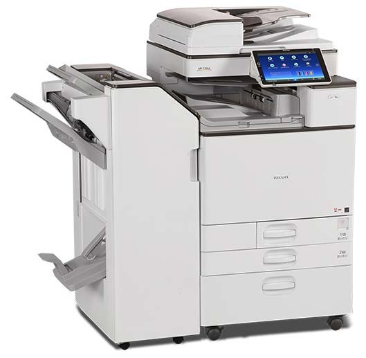
Product Overview
Product Information
PRODUCT INFORMATION
PRODUCT OVERVIEW
COMPONENT LAYOUT
For details about electrical components layout, refer to page 7-10 "Component Layout".

Product Overview
No. | Description | No. | Description |
1 | Scanner Unit | 6 | Paper Feed Unit |
2 | Paper Exit Unit | 7 | Waste Toner Unit |
3 | Fusing Unit | 8 | Laser Exposure Unit |
4 | Paper Transfer Unit | 9 | PCDU |
5 | Duplex Unit | 10 | Image Transfer Unit |
Product Overview
Product Information
PAPER PATH

No. | Description | No. | Description |
1 | SPDF DF3100 | 3 | Booklet Finisher SR3220 |
2 | Bridge Unit BU3070 | 4 | Paper Feed Unit PB3220/PB3210 |
Product Overview

No. | Description | No. | Description |
1 | ARDF DF3090 | 3 | Paper Feed Unit PB3220/PB3210 |
2 | Internal Finisher SR3130 |
Product Information
Product Overview

No. | Description | No. | Description |
1 | Platen Cover PN2000 | 4 | Side Tray Type M3 |
2 | Paper Feed Unit PB3150 | 5 | 1 Bin Tray BN3110 |
3 | Caster Table Type M3 |
Product Overview
DRIVE LAYOUT

No. | Description | No. | Description |
1 | Paper feed motor | 12 | Toner bottle drive motor (M) |
2 | Duplex/ Bypass motor | 13 | Toner bottle drive motor (Y) |
3 | Transport motor | 14 | Scanner motor |
4 | Registration motor | 15 | Toner supply motor (Y) |
5 | Paper transfer contact and release motor | 16 | Toner supply motor (M) |
6 | Fusing motor | 17 | Toner supply motor (C) |
7 | Paper exit /Pressure release motor | 18 | Toner supply motor (Bk) |
Product Information
Product Overview
No. | Description | No. | Description |
8 | Duplex entrance motor | 19 | Development motor: CMY |
9 | Reverse motor | 20 | PCU Motor: CMY |
10 | Toner bottle drive motor (Bk) | 21 | Development solenoid |
11 | Toner bottle drive motor (C) | 22 | PCU: Black/ Image transfer motor |
Machine Codes and Peripherals Configuration
MACHINE CODES AND PERIPHERALS CONFIGURATION
MAIN MACHINE
Key | Area | Power |
-17 | North America/ Central, South America | 120V/60Hz |
-18 | North America GSA models | 120V/60Hz |
-19 | Taiwan | 110V/60Hz |
-21 | China | 220-240V/50-60Hz |
-22 | China | 220-240V/50-60Hz |
-26 | Korea Narajanta model | 220V/60Hz |
-27 | Europe/ Middle, Near East | 220-240V/50-60Hz |
-29 | Korea | 220V/60Hz |
-29 | Asia/Pacific/ Central, South America | 220-240V/50-60Hz |
-65 | Europe/ Middle, Near East | 220-240V/50-60Hz |
-17
Machine Code | Product Name | DF | CPM |
D243 | MP C2004SP | ARDF 3090 Std. | FC: 20cpm/BW: 20cpm |
D244 | MP C2504SP | FC: 25cpm/BW: 25cpm |
Machine Codes and Peripherals Configuration
Product Information
-18
Machine Code | Product Name | DF | CPM |
D243 GSA | MP C2004SPG | ARDF 3090 Std. | FC: 20cpm/BW: 20cpm |
D244 GSA | MP C2504SPG | FC: 25cpm/BW: 25cpm |
-19
Machine Code | Product Name | DF | CPM |
D243 | MP C2004SP | ARDF 3090 Std. | FC: 20cpm/BW: 20cpm |
D244 | MP C2504SP | FC: 25cpm/BW: 25cpm |
-21
Machine Code | Product Name | DF | CPM |
D243 | MP C2004SP | None | FC: 20cpm/BW: 20cpm |
D244 | MP C2504SP | FC: 25cpm/BW: 25cpm |
-22
Machine Code | Product Name | DF | CPM |
D243 | DSc1220 | None | FC: 20cpm/BW: 20cpm |
D244 | DSc1225 | FC: 25cpm/BW: 25cpm |
Machine Codes and Peripherals Configuration
-26
Machine Code | Product Name | DF | CPM |
D243 | MP C2094SPJ | None | FC: 20cpm/BW: 20cpm |
D244 | MP C2594SPJ | FC: 25cpm/BW: 25cpm |
-27
Machine Code | Product Name | DF | CPM |
D243 | MP C2004SP | ARDF 3090 Std. | FC: 20cpm/BW: 20cpm |
D244 | MP C2504SP | FC: 25cpm/BW: 25cpm |
-29
Machine Code | Product Name | DF | CPM |
D243 | MP C2004SP | None | FC: 20cpm/BW: 20cpm |
D244 | MP C2504SP | FC: 25cpm/BW: 25cpm |
-65
Machine Code | Product Name | DF | CPM |
D243 | MP C2004ASP | SPDF 3100 Std. | FC: 20cpm/BW: 20cpm |
D244 | MP C2504ASP | FC: 25cpm/BW: 25cpm |
Machine Codes and Peripherals Configuration
Product Information
OPTIONS
Product Name | Code | EU | NA | AA | KOR | TWN | CHN |
SPDF DF3100 | D3B0 | N/A | N/A | -17 | -17 | -17 | -21 |
Booklet Finisher SR3220 | D3B9 | -17 | -17 | -17 | -17 | -17 | -21 |
1 Bin Tray BN3110 | D3CQ | -17 | -17 | -17 | -17 | -17 | -21 |
Bridge Unit BU3070 | D685 | -18 | -18 | -18 | -18 | -18 | -22 |
Internal Finisher SR3130 | D690 | -18 | -18 | -18 | -18 | -18 | -22 |
Side Tray Type M3 | D725 | -18 | -18 | -18 | -18 | -18 | -22 |
Internal Finisher SR3180 | D766 | -18 | -18 | -18 | -18 | -18 | -22 |
Banner Paper Guide Tray Type M19 | D3BF | -00 | -00 | -00 | -00 | -00 | -00 |
IEEE 802.11a/g/n Interface Unit Type M19 | D3BR | -01 | -01 | -01 | N/A | N/A | N/A |
Memory Unit Type M19 4GB | D3BX | -03 | -03 | -03 | -03 | -03 | -03 |
Extended USB Board Type M19 | D3BS | -01 | -01 | -01 | -01 | -01 | -01 |
IEEE 1284 Interface Board Type M19 | D3C0 | -17 | -17 | -17 | -17 | -17 | -17 |
XPS Direct Print Option Type M19 | D3BC | -24 | -25 | -26 | -26 | -26 | -26 |
USB Device Server Option Type M19 | D3BC | -28 | -29 | -29 | -29 | N/A | N/A |
PostScript3 Unit Type M19 | D3BD | -05 | 06 | -07 | -07 | -07 | -07 |
Camera Direct Print Card Type M19 | D3BD | -13 | -13 | -13 | -13 | -13 | -13 |
File Format Converter Type M19 | D3BR | -04 | -04 | -04 | -04 | -04 | -04 |
Machine Codes and Peripherals Configuration
Product Name | Code | EU | NA | AA | KOR | TWN | CHN |
DataOverwriteSecurity Unit Type M19 | D3BS | -03 | -03 | -03 | -03 | -03 | -03 |
Fax Option Type M19 | D3BV | -01 | -02 | -03 | -03 | -04 | -05 |
G3 Interface Unit Type M19 | D3BV | -07 | -08 | -08 | -08 | 12 | -08 |
Fax Memory Unit Type M19 64MB | D3BZ | -17 | -17 | -17 | -17 | -17 | -17 |
Fax Connection Unit Type M19 | D3BD | -01 | -02 | -03 | -03 | -03 | -03 |
NFC Card Reader Type M19 | D3BS | -21 | -21 | -21 | -21 | -21 | -21 |
Smart Card Reader Built-in Unit Type M19 | D3BS | -22 | -22 | -22 | -22 | -22 | -22 |
Imageable Area Extension Unit Type M19 | D3BR | -07 | -07 | -07 | -07 | -07 | -07 |
External Keyboard Bracket Type M19 | D3BR | -10 | -10 | -10 | -10 | -10 | -10 |
Punch Unit PU3050 NA | D717 | -17 | -17 | -17 | -17 | -17 | N/A |
Punch Unit PU3050 EU | D717 | -27 | -27 | -27 | -27 | -27 | -21 |
Punch Unit PU3050 SC | D717 | -28 | -28 | -28 | -28 | -28 | N/A |
Punch Unit PU3040 NA | D716 | -17 | -17 | -17 | -17 | -17 | N/A |
Punch Unit PU3040 EU | D716 | -27 | -27 | -27 | -27 | -27 | -21 |
Punch Unit PU3040 SC | D716 | -28 | -28 | -28 | -28 | -28 | N/A |
Paper Feed Unit PB3150 | D694 | -17 | -17 | -17 | -17 | -17 | -21 |
Paper Feed Unit PB3220 | D787 | -18 | N/A | -18 | -18 | -18 | -22 |
Paper Feed Unit PB3210 | D787 | N/A | -17 | N/A | N/A | N/A | N/A |
Caster Table Type M3 | D178 | -02 | -02 | -02 | -02 | -02 | -02 |
Internal Shift Tray SH3070 | D691 | -17 | -17 | -17 | -17 | -17 | -21 |
Product Information
Machine Codes and Peripherals Configuration
Product Name | Code | EU | NA | AA | KOR | TWN | CHN |
Platen Cover PN2000 | D700 | N/A | N/A | -01 | -01 | N/A | -01 |
ARDF DF3090 | D779 | N/A | N/A | -17 | -17 | -17 | -21 |
Handset HS3020 | D739 | -17 | N/A | N/A | N/A | N/A | N/A |
Marker Type 30 | H903 | -02 | -02 | -02 | N/A | -02 | N/A |
ADF Handle Type C | D593 | -81 | -81 | -81 | -81 | -81 | -81 |
RICOH e-Sharing Box | D668 | -01 | -02 | -03 | -03 | -03 | -04 |
SD Card for Fonts Type D | D641 | N/A | -54 | N/A | N/A | N/A | N/A |
Unicode Font Package for SAP(R) 1 License | B869 | -01 | -01 | -01 | -01 | -01 | -01 |
Unicode Font Package for SAP(R) 10 License | B869 | -02 | -02 | -02 | -02 | -02 | -02 |
Unicode Font Package for SAP(R) 100 License | B869 | -03 | -03 | -03 | -03 | -03 | -03 |
Optional Counter Interface Unit Type M12 | B870 | -21 | -21 | -21 | -21 | -21 | -21 |
Key Counter Bracket Type M3 | D739 | -09 | -09 | -09 | -09 | -09 | -09 |
Card Reader Bracket Type 3352 | D593 | -61 | -61 | -61 | -61 | -61 | -61 |
Bluetooth Interface Unit Type D | D566 | -01 | -01 | -01 | N/A | N/A | N/A |
Enhanced Security HDD Option Type M12 | D3A6 | -02 | -02 | N/A | N/A | N/A | N/A |
OCR Unit Type M13 | D3AC | -23 | -24 | -25 | -25 | -25 | -25 |
Machine Codes and Peripherals Configuration
DIAGRAM

No. | Item | Code | Remarks |
1 | Banner Paper Guide Tray Type M19 | D3BF-00 | Common (D238/D239/D240/D241/D242) |
2 | Paper Feed Unit PB3150 | D694-17, -21 | |
3 | Caster Table Type M3 | D178-02 | |
4 | Paper Feed Unit PB3210 (EU) Paper Feed Unit PB3220 (NA, Asia, KOR, TWN, CHN) | D787-17 D787-18, -22 | Common (D176/D177/D237) |
5 | 1 Bin Tray BN3110 | D3CQ-17, -21 | Common (D238/D239/D240/D241/D242) |
6 | Bridge Unit BU3070 | D685-18, -22 | |
7 | Internal Shift Tray SH3070 | D691-17, -21 | |
8 | Side Tray Type M3 | D725-18, -22 | |
9 | Internal Finisher SR3130 | D690-18, -22 |