![]()
Turn off the main switch and wait until the fusing unit cools down before beginning any of the procedures in this section. The fusing unit can cause serious burns.
Turn off the main power switch.
Replacement and Adjustment
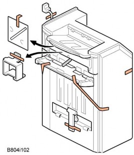
Open the right door.

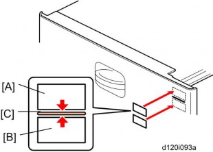
Pull up the lock levers [A].
Pull the fusing unit [B] until you hear a click.
![]()
The lock levers lock the fusing unit again at this time to prevent the fusing unit from falling down.
Pull up the lock levers [A] again, and then remove the fusing unit [B].
Fusing unit ![]() p.4-61)
p.4-61)

Web roller unit [A] ![]() x 2)
x 2)
Web roller unit ![]() p.4-62)
p.4-62)

Web left cover [A] ![]() x 1, stepped screw x 3)
x 1, stepped screw x 3)
Web top frame [B] ![]() x 2)
x 2)

Web left frame [C] ![]() x 2)
x 2)
Brake pad [D]
Replacement and Adjustment
Web roller unit ![]() p.4-62)
p.4-62)
Web left cover ![]() p.4-62 "Brake Pad")
p.4-62 "Brake Pad")
Web top frame ![]() p.4-62 "Brake Pad")
p.4-62 "Brake Pad")
Web left frame ![]() p.4-62 "Brake Pad")
p.4-62 "Brake Pad")

Front gear bracket [A] ![]() x 2)
x 2)
All gears and bushings (rear side) [B] ![]() x 2)
x 2)

Rear gear bracket [C] ![]() x 2)
x 2)
All gear and bushings (rear side) [D] ![]() x 2, spring x 1)
x 2, spring x 1)
Front bracket [E] ![]() x 2)
x 2)

Web holder roller [F] (holder x 2, spring x 2)
Web take up roller [G] ![]()
![]()
![]() )
)
Web supply roller [H] ![]()
![]()
![]() )
)

The holder [A] has a one-way clutch. Make sure that the holder [A] is set at the front side.
Replacement and Adjustment
Install the web supply roller [A] first ![]()
![]()
![]() ). Make sure that the web sheet is under the pin [B].
). Make sure that the web sheet is under the pin [B].
Install the web take up roller [C] ![]()
![]()
![]() ). Make sure that the printed number [D] is outside the web take up roller.
). Make sure that the printed number [D] is outside the web take up roller.
Reinstall the rear gear bracket ![]() p.4-63 "Web Holder Roller and Web Rollers").
p.4-63 "Web Holder Roller and Web Rollers").
Reinstall the front and rear gears and bushings ![]() p.4-63 "Web Holder Roller and Web Rollers").
p.4-63 "Web Holder Roller and Web Rollers").
Reinstall the rear gear bracket ![]() p.4-63 "Web Holder Roller and Web Rollers").
p.4-63 "Web Holder Roller and Web Rollers").

Turn the rear gear [E] in the arrow direction to remove the slack in the web sheet.
Reinstall the front gear bracket [F] ![]() p.4-63 "Web Holder Roller and Web Rollers").
p.4-63 "Web Holder Roller and Web Rollers").
Turn the coupling [G] in the arrow direction to remove the slack in the web sheet.
Reinstall the web unit.
If you install a new cleaning web, reset SP 7806-008 (press "Execute" on the LCD).
Fusing unit ![]() p.4-61)
p.4-61)

Fusing exit guide [A] (lock x 2)
Fusing front upper cover [B] ![]() x 3)
x 3)
Fusing rear upper cover [C] ![]() x 3)
x 3)
Fusing outer guide [D] (front: ![]() x 1, rear: stepped screw x 1)
x 1, rear: stepped screw x 1)

Cleaning roller unit [E] ![]() x 4)
x 4)
Pressure roller cleaning roller [F] (spring x 2, holder x 2)
Replacement and Adjustment
Fusing unit ![]() p.4-61)
p.4-61)
Web roller unit ![]() p.4-62)
p.4-62)

Fusing top cover [A] (front: ![]() x 1, rear: stepped screw x 1)
x 1, rear: stepped screw x 1)
Thermostat holder [B] ![]() x 2)
x 2)
Thermostat cover [C] ![]() x 2)
x 2)
Thermostat [D] (terminal x 2)
Fusing unit ![]() p.4-61)
p.4-61)
Web roller unit ![]() p.4-62)
p.4-62)
Fusing top cover ![]() p.4-67 "Thermostats")
p.4-67 "Thermostats")
Pull the two tabs [A].
Disconnect the two terminals [B].
Sensor stays [C] ![]() x 1 each)
x 1 each)
Thermistors [D] ![]() x 2,
x 2, ![]() x 1)
x 1)
Fusing unit ![]() p.4-61)
p.4-61)
Web roller unit ![]() p.4-62)
p.4-62)
Fusing top cover ![]() p.4-67 "Thermostats")
p.4-67 "Thermostats")
Replacement and Adjustment
Fusing top frame [A] ![]() x 5)
x 5)
![]()
The cords on this frame are still connected to the fusing unit at this time. Be careful not to damage the cords when removing the hot roller stripper [B].
Hot roller stripper [B] (spring x 1)
Fusing unit ![]() p.4-61)
p.4-61)
Web roller unit ![]() p.4-62)
p.4-62)
Fusing top cover ![]() p.4-67 "Thermostats")
p.4-67 "Thermostats")

Connector cover [A] ![]() x 2)
x 2)
Fusing top frame with connector [B] ![]() x 9)
x 9)

Fusing front lower cover [C] ![]() x 2)
x 2)
Fusing front frame [D] ![]() x 3)
x 3)
Fusing rear lower cover [E] ![]() x 2)
x 2)
Fusing rear frame [F] ![]() x 5)
x 5)

Terminal bracket [G] ![]() x 4)
x 4)
Front holder bracket [H] ![]() x 1)
x 1)
Terminal base [I] ![]() x 3)
x 3)
Rear holder bracket [J] ![]() x 1)
x 1)
Replacement and Adjustment
Fusing lamp-Center (550W) [K]
Fusing lamp-End (750W) [L]
Fusing lamps-Center and End ![]() p.4-70 "Fusing Lamps")
p.4-70 "Fusing Lamps")

Hot roller [A] (snap ring x 2, gear x 2, bushing x 2)
Pressure roller [B] ![]() x 2, bushing x 2)
x 2, bushing x 2)
Fusing unit ![]() p.4-61)
p.4-61)
Fusing exhaust fan duct ![]() p.4-106 "Fusing Exhaust Fan")
p.4-106 "Fusing Exhaust Fan")

Paper exit unit [A] ![]() x 3,
x 3, ![]() x 2)
x 2)

Replacement and Adjustment
Paper exit unit ![]() p.4-72)
p.4-72)
Sensor bracket [A] ![]() x 1)
x 1)
Paper exit sensor [B] ![]() x 1, hooks)
x 1, hooks)
Paper overflow sensor [C] ![]() x 1, hooks)
x 1, hooks)
Sensor bracket [D] ![]() x 2)
x 2)
Fusing exit sensor [E] ![]() x 1,
x 1, ![]() x 1)
x 1)

Paper exit unit ![]() p.4-72)
p.4-72)
Paper guide [A] ![]() x 3)
x 3)
Junction jam sensor [B] ![]() x 1)
x 1)
Paper exit unit ![]() p.4-72)
p.4-72)

Motor cover [A] ![]() x 1)
x 1)
Exit motor [B] ![]() x 2,
x 2, ![]() x 2,
x 2, ![]() x 1)
x 1)
Right rear cover ![]() p.4-5)
p.4-5)

Replacement and Adjustment
Open the lower right cover [A] at the duplex unit.
Release the tab [B] and remove the lower door (spring x 2).
Open the right door.

Release the front link [C] ![]() x 1).
x 1).

Keep the right door fully open.

Push up the duplex unit a little bit, while pressing the bracket [D] to lock the spring [E].
![]()
Do not let the duplex unit open fully before releasing the wire (step 9). Otherwise, the lock for the spring [E] is released.
Wire [F] ![]() x 1)
x 1)
Push the projection [G].
Duplex unit ![]() x 3,
x 3, ![]() x 1, ground cable x 1)
x 1, ground cable x 1)

Replacement and Adjustment
Open the duplex door [A] and by-pass tray.
Right door cover [B] ![]() x 4)
x 4)
Right door cover ![]() p.4-77)
p.4-77)

Duplex door sensor [A] ![]() x 1, hook)
x 1, hook)
Right door cover ![]() p.4-77)
p.4-77)
Open the right door.
Duplex entrance guide [A] ![]() x1, [C]: Stepped screw x 2)
x1, [C]: Stepped screw x 2)
Duplex entrance sensor bracket [A] ( x 1,
x 1)
4.

5. Duplex entrance sensor [A] (hooks)
Transfer belt unit ![]() p.4-50)
p.4-50)

Replacement and Adjustment
Right door rear cover [A] ![]() x 3)
x 3)

Remove the shaft [B] ![]() x 1).
x 1).
Transfer belt unit holder [C] ![]() x 1,
x 1, ![]() x 1)
x 1)
![]()
When re-installing the transfer belt unit holder, make sure that the spring [D] correctly hooks onto the frame.

Guide plate [E] (two hooks)
Duplex exit sensor [F] ![]() x 1, hooks)
x 1, hooks)
Rear cover ![]() p.4-4)
p.4-4)
Right rear cover ![]() p.4-5)
p.4-5)

Replacement and Adjustment
Frame [A] ![]() x 4)
x 4)
Duplex/By-pass motor bracket [B] ![]() x 2,
x 2, ![]() x 1)
x 1)

Duplex/By-pass motor [C] ![]() x 4, bushing x 8, timing belt x 1)
x 4, bushing x 8, timing belt x 1)
Right door cover ![]() p.4-77)
p.4-77)
Open the right door.
Right door rear cover [A] ![]() x 3)
x 3)
Duplex door [B]
Duplex guide plate [C] ![]() x 3)
x 3)

Bracket [D] ![]() x 2)
x 2)
Replacement and Adjustment
Duplex inverter motor [E] ![]() x 3,
x 3, ![]() x 1)
x 1)
Open the lower right cover [A].

Disconnect the connector and clamp.

Open the by-pass tray [A].

Move the side fences to the center.
Replacement and Adjustment
By-pass tray cover [A] ![]() x 4)
x 4)

By-pass paper size sensor [A] ![]() x 1)
x 1)
By-pass paper length sensor [B] ![]() x 1)
x 1)
Adjust the projection [A] of the left side fence bar (it must be centered).
Install the by-pass paper size detection switch so that the hole [B] in this switch faces the projection [C] of the left side fence bar.
Reassemble the copier.
Plug in and turn on the main power switch.
Check this switch operation with SP5803-024 (By-pass: Paper Size Sensor< Input Check).
Paper Size | Display | Paper Size | Display |
A3 SEF | 00001110 | A5 SEF | 00001011 |
B4 SEF | 00001100 | B6 SEF | 00000011 |
A4 SEF | 00001101 | A6 SEF | 00000111 |
B5 SEF | 00001001 | Smaller A6 SEF | 00001111 |
Right door cover ![]() p.4-77 "Right Door Cover")
p.4-77 "Right Door Cover")

Replacement and Adjustment
By-pass feed unit cover [A] ![]() x 2).
x 2).
By-pass paper end sensor [B] ![]() x 1, hooks)
x 1, hooks)
Right door cover ![]() p.4-77)
p.4-77)
By-pass feed unit cover ![]() p.4-87 "By-pass Paper End Sensor")
p.4-87 "By-pass Paper End Sensor")
By-pass pick-up roller [A] (hook)
By-pass feed roller [B] ![]() x 1)
x 1)
By-pass separation roller [C] ![]() x 1)
x 1)
Torque limiter [D]
Open the right door.
Right door rear cover ![]() p.4-79 "Duplex Exit Sensor")
p.4-79 "Duplex Exit Sensor")
Transfer belt unit ![]() p.4-50)
p.4-50)
Transfer belt unit holder ![]() p.4-79 "Duplex Exit Sensor")
p.4-79 "Duplex Exit Sensor")

By-pass feed clutch holder [A] ![]() x 2)
x 2)
By-pass feed clutch [B] ![]() x 1,
x 1, ![]() x 1)
x 1)
Rear cover ![]() p.4-4)
p.4-4)

Replacement and Adjustment
Clutch bracket [A] ![]() x 2,
x 2, ![]() x 1, bushing x 1)
x 1, bushing x 1)
Paper feed clutch [B] ![]() x 1)
x 1)
Rear cover ![]() p.4-4)
p.4-4)

Development paddle motor [A] ![]() x 4,
x 4, ![]() x 1)
x 1)
Rear cover ![]() p.4-4)
p.4-4)

Transfer/development motor [A] ![]() x 4,
x 4, ![]() x 1)
x 1)
Rear cover ![]() p.4-4)
p.4-4)

Replacement and Adjustment
Drum motor [A] ![]() x 4,
x 4, ![]() x 1)
x 1)
Rear cover ![]() p.4-4)
p.4-4)

Fusing motor [A] ![]() x 4,
x 4, ![]() x 1)
x 1)
Rear cover ![]() p.4-4)
p.4-4)

Bracket [A] ![]() x 1)
x 1)
Web motor [B] ![]() x 1,
x 1, ![]() x 1)
x 1)
Rear cover ![]() p.4-4)
p.4-4)
Right rear cover ![]() p.4-5)
p.4-5)
Paper feed motor [A] ![]() x 2,
x 2, ![]() x 1)
x 1)
Rear cover ![]() p.4-4)
p.4-4)
Right rear cover ![]() p.4-5)
p.4-5)

Transfer belt contact motor [A] ![]() x 2,
x 2, ![]() x 1)
x 1)
Replacement and Adjustment
Rear cover ![]() p.4-4)
p.4-4)
Right rear cover ![]() p.4-5)
p.4-5)

Registration motor bracket [A] ![]() x 3,
x 3, ![]() x 1)
x 1)
Registration motor [B] ![]() x 2,
x 2, ![]() x 1)
x 1)
Left cover ![]() p.4-4)
p.4-4)
Upper inner cover ![]() p.4-3 "Front Door, Upper and Lower Inner Cover")
p.4-3 "Front Door, Upper and Lower Inner Cover")
Inner Tray ![]() p.4-9)
p.4-9)
Exhaust duct [A] ( x 2)
4.
5. Toner supply motor [B] (hooks, ![]() x 1)
x 1)

Replacement and Adjustment
1. Controller unit [A] ![]() x 2)
x 2)
Copy the address book data to an SD card from the HDD with SP5846-051 if possible.
Controller unit ![]() p.4-95)
p.4-95)
HDD unit [A] with connecting board [B] ![]() x 3,
x 3, ![]() x 2)
x 2)

Replacement and Adjustment
HDD unit [A] ![]() x 2,
x 2, ![]() x 2)
x 2)
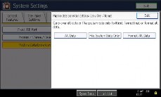
Do SP5832-001 to format the hard disk.
Do SP5853-001 to copy the preset stamp data from the firmware to the hard disk.
Do SP5846-052 to copy back the address book to the hard disk from the SD card to which you have already copied the address book data if possible.
Turn the main power switch off/on.
Never remove an HDD unit from the work site without the consent of the client.
If the customer has any concerns about the security of any information on the HDD, the HDD must remain with the customer for disposal or safe keeping.
The HDD may contain proprietary or classified (Confidential, Secret) information. Specifically, the HDD contains document server documents and data stored in temporary files created automatically during copy job sorting and jam recovery. Such data is stored on the HDD in a special format so it cannot normally be read but can be recovered with illegal methods.
Explain to the customer that the following information stored on the HDD is lost when the HDD is replaced: document server documents, fixed stamps, document server address book
The address book and document server documents (if needed) must be input again.
![]()
The battery on the control board can explode if replaced incorrectly.
Dispose of the old battery in accordance with the instructions.
When you replace the controller board in a model without a HDD, address book data can be copied from an old controller board to a new controller board using an SD card.
Copy the address book data to an SD card from the flash ROM on the controller board with
Controller unit ![]() p.4-95)
p.4-95)
HDD unit (if it has been installed.) ![]() p.4-96)
p.4-96)
Controller cover [A] ![]() x 2)
x 2)

Replacement and Adjustment
Controller right bracket [A] ![]() x 5)
x 5)

Controller board assembly [A] ![]() x 4, connector caps)
x 4, connector caps)

NVRAMs [A]
Interface rails [B] (hooks each)
DIMM-RAM (If it is installed.)
Controller board [C]
Remove the NVRAMs from the old controller board.
Install them on the new controller board after you replace the controller board.
Replace the NVRAMs if the NVRAM on the old controller board is defective.
![]()
Make sure you print out the SMC reports ("SP Mode Data" and "Logging Data") before you replace the NVRAMs.
![]()
Keep NVRAMs away from any objects that can cause static electricity. Static electricity can damage NVRAM data.
Make sure the NVRAMs are correctly installed on the controller board.
Make sure that the DIP-switch settings on the old controller board are the same for the new controller board. Do not change the DIP switches on the controller board in the field.
For a model without a HDD, do SP5846-052 to copy back the address book to the flash ROM on the controller board from the SD card to which you have already copied the address book data if possible.
If the customer is using the data encryption feature, the encryption key must be restored.
Turn the main power switch off/on.
Rear cover ![]() p.4-4)
p.4-4)
Replacement and Adjustment
Controller unit ![]() p.4-95)
p.4-95)

Exhaust fan duct [A] ![]() x 2,
x 2, ![]() x 1)
x 1)

Controller box [A] ![]() x 6,
x 6, ![]() x 4,
x 4, ![]() x 3)
x 3)

Mother board [A] ![]() x 6)
x 6)
1. Controller box ![]() p.4-101 "Mother Board")
p.4-101 "Mother Board")

Replacement and Adjustment
2. BCU [A] ![]() x 4,
x 4, ![]() x 4)
x 4)

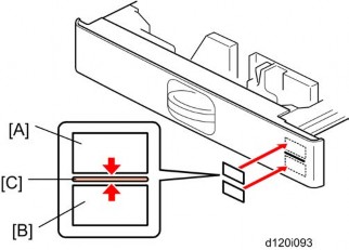
Remove the NVRAM [A] from the old board and install it on the new board.
Set the DIP switches on the new BCU board to the same settings as the old board.
![]()
Make sure the NVRAM is correctly installed on the BCU. Insert the NVRAM in the NVRAM slot with the "half-moon" pointing [B] to the left side.
Remove the NVRAM from the old BCU.
Install the NVRAM on the new BCU after you replace the BCU.
Reassemble the machine.
Turn on the main power switch. 5. "SC995-01" occurs.
Enter the serial number with SP5-811-004.
Turn the main power switch off and on.
![]()
Make sure you print out the SMC reports ("SP Mode Data" and "Logging Data") before you replace the NVRAM.
![]()
Keep NVRAM away from any objects that can cause static electricity. Static electricity can damage NVRAM data.
Controller box ![]() p.4-101 "Mother Board")
p.4-101 "Mother Board")

IPU[[A] ![]() x 6,
x 6, ![]() x all)
x all)
Rear cover ![]() p.4-4)
p.4-4)

Replacement and Adjustment
IOB [A] ![]() x 6,
x 6, ![]() x all)
x all)
Set the bit switches on the new IOB to the same settings as the old IOB.
Left cover ![]() p.4-4)
p.4-4)

PSU [A] ![]() x 4,
x 4, ![]() x all)
x all)
Two clamps [B] (These clamps will be used for the new PSU.)
Rear cover ![]() p.4-4)
p.4-4)
Right rear cover ![]() p.4-5)
p.4-5)

High voltage power supply board [A] ![]() x 5,
x 5, ![]() x all)
x all)
Rear cover ![]() p.4-4)
p.4-4)

Fusing exhaust duct [A] ![]() x 2,
x 2, ![]() x 1)
x 1)
Separate the duct (hooks).
Fusing exhaust fan [B]
Make sure that the fusing fan is installed with its decal facing the right side of the machine.
Controller box ![]() p.4-101 "Mother Board")
p.4-101 "Mother Board")

Fan cover [A] ![]() x 2)
x 2)
Replacement and Adjustment
Controller fan [B] ![]() x 1)
x 1)
Make sure that the controller fan is installed with its decal facing upward.
Electrical Components
Rev. 1/4/2013
4.15.13 NVRAM ON THE BCU BOARD
Turn the main power switch ON.
Access SP5990-001 and print out all data lists.
Turn the main power switch OFF.
Insert the SD card into the lower slot on the controller box.
Turn the main power switch ON.
Upload the NVRAM data (SP5-824-001) onto the SD card.
Turn the main power switch OFF.
Remove the old NVRAM from the BCU and attach the new one.
Access SP5807-001 and set the area code.
The initial value stored in the NVRAM is “1”.
After the NVRAM is replaced, the display for SP5807-001 changes to Japanese.
Refer to the following area destination code list.
Area code | Destination |
1 | JP |
2 | NA |
3 | EU |
4 | TWN |
5 | AA |
6 | CHN |
7 | KOR |
Access SP5-811-001 and program the machine serial number.
Access SP5-811-004 and program the BCU serial number.
Turn the main switch off.
Download the NVRAM data (SP5-825-001) stored on the SD card in Step 5 onto the machine.
Remove the SD card from the lower slot in the controller box.
Important: If you cannot upload the NVRAM data (SP5-824-001) or download the NVRAM data (SP5-825-001), do the following:
-Enter the data from the SMC report manually (included in the factory sheet).
-Reinstall the security options (Data Overwrite Security, HDD Encryption).
Rev. 12/27/2012
Copy Adjustments: Printing/Scanning
Perform these adjustments after replacing any of the following:
Scanner Wire
Lens Block/SBU Assembly
Scanner Drive Motor
Polygon Mirror Motor
Paper Side Fence
Memory All Clear
Replacement and Adjustment
Make sure paper is installed correctly in each paper tray before you start these adjustments.
Use the Trimming Area Pattern (SP2-109-1, No. 14) to print the test pattern for the following procedures.

Check the leading edge registration [A] for each paper type and paper feed station, and adjust it with following SP modes.
SP No. | Specification | |
Tray: Plain | SP1-001-1 | 0 ±9.0 mm |
Tray: Thick 1 | SP1-001-2 |
Copy Adjustments: Printing/Scanning
Rev. 12/27/2012
SP No. | Specification | |
Tray: Thick 2 | SP1-001-3 | |
By-pass: Plain | SP1-001-4 | |
By-pass: Thick 1 | SP1-001-5 | |
By-pass: Thick 2 | SP1-001-6 | |
Duplex: Plain | SP1-001-7 | |
Duplex: Thick 1 | SP1-001-8 |
Check side-to-side registration [B] for each paper feed station, and adjust with the following SP modes.
SP No. | Specification | |
By-pass | SP1-002-1 | 0 ±4.0 mm |
Tray 1 | SP1-002-2 | |
Tray 2 | SP1-002-3 | |
Tray 3 | SP1-002-4 | |
Tray 4 | SP1-002-5 | |
LCT | SP1-002-6 | |
Duplex | SP1-002-7 |