Replacement and Adjustment
Rev. 09/11/2012
Exterior Covers
Left cover ( p.4-4)
Upper inner cover ( p.4-3 "Front Door, Upper and Lower Inner Cover")
Paper exit cover ( p.4-8)

Connector cover [A]
Inner rear cover [A]

Inner tray [A]
Scanner
Rev. 09/11/2012

Glass cover [A] ( x 2)
ARDF exposure glass [B]
Rear scale [C] ( x 3)
Exposure glass with left scale [D]
Position the white marker [E] at the rear-left corner and the black or blue marker at the front-left corner when you reattach the ARDF exposure glass.
1. Remove the Operation Panel ( 4.3.6)

1. Scanner left cover [A] ( x 3)
Replacement and Adjustment
Rev. 09/11/2012 Scanner

1. Scanner right cover [A] ( x 2)
Operation panel ( p.4-7)

Scanner front cover [A] ( x 2)

1. Scanner rear cover [A] ( x 1)
Exposure glass ![]() p.4-10)
p.4-10)
Scanner right cover ![]() p.4-11 "Scanner Exterior Panels and Operation Panel")
p.4-11 "Scanner Exterior Panels and Operation Panel")
SBU cover [A] ( x 4)
3.
Original size sensor bracket ![]() p.4-15 "Original Size Sensor")
p.4-15 "Original Size Sensor")

Lens block assembly [A] ![]() x 4, Grand screw x 1,
x 4, Grand screw x 1, ![]() x 2)
x 2)
![]()
Do not remove the other screws on the lens block unit.
Adjust the following SP modes after you replace the lens block assembly:
SP4–008 (Sub Scan Mag): ![]() "Scanning" in "Copy Adjustments: Printing/Scanning")
"Scanning" in "Copy Adjustments: Printing/Scanning")
SP4–010 (Sub Mag Reg.): ![]() "Scanning" in "Copy Adjustments: Printing/Scanning")
"Scanning" in "Copy Adjustments: Printing/Scanning")
SP4–011 (Main Scan Reg): ![]() "Scanning" in "Copy Adjustments: Printing/Scanning")
"Scanning" in "Copy Adjustments: Printing/Scanning")
SP4–688 (DF: Density Adjustment): Use this to adjust the density level if the ID of outputs made in the DF and Platen mode is different.
Exposure glass with left scale ![]() p.4-10 "Exposure Glass")
p.4-10 "Exposure Glass")
Scanner right cover ![]() p.4-11 "Scanner Exterior Panels and Operation Panel")
p.4-11 "Scanner Exterior Panels and Operation Panel")
Replacement and Adjustment
SBU cover ![]() p.4-14 "Lens Block Assembly")
p.4-14 "Lens Block Assembly")

Remove the screw [A] on the sensor board bracket.

Circuit chip [A] ![]() x 1,
x 1, ![]() x 1)
x 1)

Original size sensor bracket [A] ![]() x 2)
x 2)

Original size sensors [A] (hooks)
![]()
Before replacing the scanner lamp, check and note the first three digits in the bar-code on the new scanner lamp ![]() “Chromaticity rank adjustment” in this section).
“Chromaticity rank adjustment” in this section).
Operation panel ![]() p.4-7)
p.4-7)
Exposure glass ![]() p.4-10)
p.4-10)
Scanner front cover ![]() p.4-11 "Scanner Exterior Panels and Operation Panel")
p.4-11 "Scanner Exterior Panels and Operation Panel")

Replacement and Adjustment
Move the first scanner carriage [A] to the position shown above.

Remove the two screws on the scanner lamp [A].

Disconnect the connector [A] on the scanner lamp.

Pull out the scanner lamp [A].
Each scanner lamp has a specific chromaticity rank. The chromaticity rank is indicated by the bar-code on the new scanner lamp. After replacing the lamp, adjust the chromaticity rank to correspond to the new scanner lamp.

Check the first three digits [A] in the bar-code on the new scanner lamp before installing the new lamp.
Replacement and Adjustment
After installing the new lamp, go to SP4-954-005 and enter the SP setting number referring to the table below.
1st Three Digits | SP Setting (SP4-954-005) | 1st Three Digits | SP Setting (SP4-954-005) |
139 | 3 | 166 | 12 |
140 | 2 | 167 | 11 |
141 | 1 | 168 | 10 |
142 | 6 | 169 | 15 |
143 | 5 | 170 | 14 |
144 | 4 | 171 | 13 |
145 | 9 | 172 | 18 |
146 | 8 | 173 | 17 |
147 | 7 | 174 | 16 |
148 | 12 | 204 | 3 |
149 | 11 | 205 | 2 |
150 | 10 | 206 | 1 |
151 | 15 | 207 | 6 |
152 | 14 | 208 | 5 |
153 | 13 | 209 | 4 |
154 | 18 | 210 | 9 |
155 | 17 | 211 | 8 |
156 | 16 | 212 | 7 |
157 | 3 | 213 | 12 |
158 | 2 | 214 | 11 |
159 | 1 | 215 | 10 |
160 | 6 | 216 | 15 |
1st Three Digits | SP Setting (SP4-954-005) | 1st Three Digits | SP Setting (SP4-954-005) |
161 | 5 | 217 | 14 |
162 | 4 | 218 | 13 |
163 | 9 | 219 | 18 |
164 | 8 | 220 | 17 |
165 | 7 | 221 | 16 |
Scanner rear cover ![]() p.4-11 "Scanner Exterior Panels and Operation Panel")
p.4-11 "Scanner Exterior Panels and Operation Panel")
Exposure glass ![]() p.4-10)
p.4-10)

Move the 1st scanner carriage [A] to the right side.

Remove the mylar [A].

Remove the scanner HP sensor [A] ![]() x 1, three snaps)
x 1, three snaps)
Replacement and Adjustment
Scanner rear cover ![]() p.4-11 "Scanner Exterior Panels and Operation Panel")
p.4-11 "Scanner Exterior Panels and Operation Panel")

Platen cover sensor [A] ![]() x 1,
x 1, ![]() x 1)
x 1)
Scanner rear cover ![]() p.4-11 "Scanner Exterior Panels and Operation Panel")
p.4-11 "Scanner Exterior Panels and Operation Panel")

Remove the 8 screws of the scanner rear frame [A].

Disconnect the two connectors.

Pull over the scanner rear stay [A] and remove it ![]() x 2,
x 2, ![]() x 3).
x 3).
Scanner motor bracket [A] ( x 1)
Replacement and Adjustment
5.
Scanner motor [A] ( x 2,
x 1, spring x 1, belt x 1)
6.
![]()
After replacing the scanner motor, do the image adjustments in the following section of the manual ![]() "Scanning" in "Copy Adjustments: Printing/Scanning").
"Scanning" in "Copy Adjustments: Printing/Scanning").
Scanner rear cover ![]() p.4-11 "Scanner Exterior Panels and Operation Panel")
p.4-11 "Scanner Exterior Panels and Operation Panel")
Scanner rear stay. ![]() p.4-22 "Scanner Motor")
p.4-22 "Scanner Motor")

SIO [A] ![]() x 4,
x 4, ![]() x All)
x All)
Scanner front cover ![]() p.4-11 "Scanner Exterior Panels and Operation Panel")
p.4-11 "Scanner Exterior Panels and Operation Panel")
Scanner left cover ![]() p.4-11 "Scanner Exterior Panels and Operation Panel")
p.4-11 "Scanner Exterior Panels and Operation Panel")

Scanner left stay [A] ![]() x 3)
x 3)
Scanner left rail frame [B].

Replacement and Adjustment
Operation panel stay [A] ![]() x 5,
x 5, ![]() x 1)
x 1)

Scanner front stay [A] ![]() x 5)
x 5)
To make reassembly easy, slide the 1st scanner carriage to the right.

Front scanner wire clamp [A]
Front scanner wire bracket [B] ![]() x 1)
x 1)
Front scanner wire and scanner drive pulley [C] ![]() x 1)
x 1)

Position the center ball [A] in the middle of the forked holder.
Pass the right end (with the ball) [B] through the square hole. Pass the left end (with the ring) [C] through the notch.
Wind the right end counterclockwise (shown from the machine’s front) five times. Wind the left end clockwise twice.
![]()
The two red marks [D] come together when you have done this. Stick the wire to the pulley with tape. This lets you easily handle the assembly at the time of installation.

Install the drive pulley on the shaft [E].
![]()
Replacement and Adjustment
Do not attach the pulley to the shaft with the screw at this time.
Insert the left end into the slit [F]. The end should go via the rear track of the left pulley [G] and the rear track of the movable pulley [H].

Hook the right end onto the front scanner wire bracket [I]. The end should go via the front track of the right pulley [J] and the front track of the movable pulley [K].
![]()
Do not attach the scanner wire bracket with the screw at this time.

Remove the tape from the drive pulley.
Insert a scanner-positioning pin [L] through the 2nd carriage hole [M] and the left holes [N] in the front rail. Insert another scanner positioning pin [O] through the 1st carriage hole [P] and the right holes in the front rail [Q].
Insert two more scanner positioning pins through the holes in the rear rail.
Screw the drive pulley to the shaft [R].
Screw the scanner wire bracket to the front rail [S].
Install the scanner wire clamp [T].
Pull out the positioning pins.
![]()
Make sure the 1st and 2nd carriages move smoothly after you remove the positioning pins. Do steps 8 through 13 again if they do not.
After replacing the scanner wire, do the image adjustments in the following section of the manual ![]() "Scanning" in "Copy Adjustments: Printing/Scanning").
"Scanning" in "Copy Adjustments: Printing/Scanning").
Scanner front cover ![]() p.4-11 "Scanner Exterior Panels and Operation Panel")
p.4-11 "Scanner Exterior Panels and Operation Panel")
Scanner left cover ![]() p.4-11 "Scanner Exterior Panels and Operation Panel")
p.4-11 "Scanner Exterior Panels and Operation Panel")
Scanner left stay ![]() p.4-24 "Front Scanner Wire")
p.4-24 "Front Scanner Wire")
Scanner left rail frame ![]() p.4-24 "Front Scanner Wire")
p.4-24 "Front Scanner Wire")
Scanner rear cover ![]() p.4-11 "Scanner Exterior Panels and Operation Panel")
p.4-11 "Scanner Exterior Panels and Operation Panel")
Scanner rear stay ![]() p.4-22 "Scanner Motor")
p.4-22 "Scanner Motor")

Replacement and Adjustment
Rear rail frame [A] ![]() x 5)
x 5)
SIO ![]() p.4-24 "Scanner Motor Drive Board")
p.4-24 "Scanner Motor Drive Board")

To make reassembly easy, slide the first scanner to the center.
Rear scanner wire clamp [B]
Rear scanner wire bracket [C] ![]() x 1)
x 1)
Scanner motor gear [D] ![]() x 1)
x 1)
Rear scanner wire and scanner drive pulley [E] ![]() x 1)
x 1)
Position the center ball [B] in the middle of the forked holder.
Pass the end with the ball [A] through the right square hole from the front.
Position the center ball [B] in the middle of the notch, as shown by the arrow.
Pass the ball end [A] through the drive pulley notch.
Wind the end with the ring [C] clockwise (shown from the machine’s front) three times; wind the ball end [A] clockwise (shown from the machine’s front) five times.
![]()
The two red marks [D] should meet when you have done this.
Stick the wire to the pulley with tape, so you can easily handle the pulley and wire during installation.
Install the drive pulley on the shaft.
![]()
Do not screw the pulley onto the shaft yet.
Install the wire.
![]()
The winding of the wire on the three pulleys at the rear of the scanner should be the same as the winding on the three pulleys at the front. This must show as a mirror image. Example: At the front of the machine, the side of the drive pulley with the three windings must face the front of the machine. At the rear of the machine, it must face the rear.
Perform steps 8 through 13 in “Reassembling the Front Scanner Wire”.
![]()
After replacing the scanner wire, do the image adjustments in the following section of the manual ![]() "Scanning" in "Copy Adjustments: Printing/Scanning").
"Scanning" in "Copy Adjustments: Printing/Scanning").
![]()
Turn off the main power switch and unplug the machine before attempting any of the procedures in this section. Laser beams can seriously damage your eyes.

Replacement and Adjustment
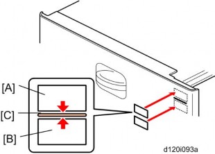
Two caution decals are located in the laser section as shown below. (See the next page for removal instructions.)

Open the front door.
Front door [A] (pins x 2)
Upper inner cover [B] ![]() x 2)
x 2)
Glass cap [C]
Shield glass [D]
Lower inner cover [E] ![]() x 2)
x 2)

Laser unit connectors [E] ![]() x 3,
x 3, ![]() x 1)
x 1)
![]()
Do not disconnect the harnesses on the LD board [F] unless the LD unit has to be replaced. This board is precisely adjusted in the factory.
Laser unit [G] ![]() x 2)
x 2)
![]()
When sliding out the laser unit, do not hold the LD board. Hold the laser unit.
Replacement and Adjustment
Laser unit ![]() p.4-31)
p.4-31)
Laser unit cover [A] ![]() x 4)
x 4)
Polygon mirror motor [B] ![]() x 4,
x 4, ![]() x 1)
x 1)
After replacing the polygon mirror motor, do the image adjustment ![]() p.4-108 "Copy Adjustments: Printing/Scanning").
p.4-108 "Copy Adjustments: Printing/Scanning").
Laser unit ![]() p.4-31)
p.4-31)

Laser synchronization detector [A] ![]() x1,
x1, ![]() x1)
x1)
Laser unit ![]() p.4-31)
p.4-31)

Upper spring plate [A] ![]() x 1)
x 1)
Lower spring plate [B] ![]() x 1)
x 1)
LD unit [C] ![]() x 1,
x 1, ![]() x1, spring x 1)
x1, spring x 1)
![]()
To avoid damaging the LD board, hold it securely when disconnecting the connectors. Hold the laser unit casing.
After replacing the LD board, do the "Laser Beam Pitch Adjustment" (described in the following section). Keep the lower inner cover removed before doing this adjustment because you need to adjust the adjustor screw [D] on the LD unit with a screwdriver.

Install a (new) LD unit [A] with the left side of the LD unit being lower than the right side. (This makes this adjustment easier.)
Print the test pattern "Hounds Tooth Check (2-Dot Horizontal)" (No. 16 in SP2109-001).
Check if the vertical stripes appear on the second pattern (counted from the leading edge) of the printout.
Correct: No vertical stripes appear (see the sample following this procedure.)
Wrong: Vertical stripes appear (see the sample following this procedure.)
Turn the adjustor screw [B] by 90 degrees clockwise (counterclockwise).
![]()
If the image of the printout is getting worse, try reverse rotation (clockwise ![]() counterclockwise)
counterclockwise)
Print the test pattern and check it out.
Try steps 2 to 4 again until you get an image with no vertical stripes.
Reassemble the machine after completing this adjustment.
Replacement and Adjustment


Open the front door.
Replacement and Adjustment
Open the right door [A].
Release the lock lever [B].
Pull out the PCDU [C] and place it on a clean flat surface.
Spread a large piece of paper on a flat surface.
![]()
Make sure the area is free of pins, paper clips, staples, etc. to avoid attraction to the magnetic development roller.
Open the right cover before you install the PCDU in the machine.
Remove the PCDU ![]() p.4-37)
p.4-37)
Toner cap [A]
Insert cap [A] into the opening of the PCDU [B].
![]()
Make sure that the cap is inserted completely into the opening.

Open the PCDU [C] ![]() x 2).
x 2).
Bracket [D] ![]() x 1)
x 1)

![]()
Pull the drum [E] towards the front ![]() (the left side in the illustration) while releasing the charge roller [F] using the release levers
(the left side in the illustration) while releasing the charge roller [F] using the release levers ![]() [G], and then remove the drum
[G], and then remove the drum ![]() .
.
Replacement and Adjustment
Never touch the drum surface with bare hands.
Replace the drum and close the PCDU ![]() x 2).
x 2).
Put the opening cap [A in the previous procedure] back in its original place.
After replacing the drum, do these SPs:
SP 2001: Charge Bias Setting – make sure that this is at the default setting
SP 3001-2: P Sensor Initial Setting (P sensor = ID Sensor)
SP 2805: Process Setting
SP 2810-1: Grayscale Setting
1. Drum ![]() p.4-38)
p.4-38)

Pawl assembly [A]
Pick-off pawl [B] (spring x 1, spur x 1)
If the pick-off pawl has marked the drum with a line, the pick-off pawl position can be adjusted using either method:
Changing the spur position
Changing the pick-off pawl assembly position
1. Drum ![]() p.4-38)
p.4-38)

Replacement and Adjustment
Push the charge roller holder [A] toward the front of the drum ![]() x 2) and remove the spring [B].
x 2) and remove the spring [B].
Charge roller [C].
![]()
Disengage the charge roller on the right side to remove it. Try to avoid touching the charge roller.
Cleaning roller [D]
![]()
Disengage the cleaning roller on the left to remove it.
After replacing the charge roller and cleaning roller, check the value of SP2001-001. If it is not at the standard value (1500), set SP2001-001 to "1500".
![]()
If this is not done, the carrier will be attracted to the drum because the charge roller voltage will be too high.
1. Drum ![]() p.4-38)
p.4-38)
Charge roller and cleaning roller ![]() p.4-41)
p.4-41)

Remove drum cleaning blade [A] ![]() x 2)
x 2)
Put toner on the edge of cleaning blade and the mylar at the back side of cleaning blade before re-installing this blade.
1. PCDU ![]() p.4-37)
p.4-37)
Fusing unit ![]() p.4-61)
p.4-61)

Replacement and Adjustment
ID sensor bracket [A] ![]() x 2,
x 2, ![]() x 1)
x 1)
ID sensor [B] ![]() x 1)
x 1)
![]()
Do SP3-001-002 to initialize the ID sensor after replacing.
1. PCDU ![]() p.4-37)
p.4-37)
Open the PCDU. ![]() p.4-38 "Drum")
p.4-38 "Drum")

Upper development cover [A] ![]() x2)
x2)
Development filter [B]
1. PCDU ![]() p.4-37)
p.4-37)
Open the PCDU. ![]() p.4-38 "Drum")
p.4-38 "Drum")
Upper development cover ![]() p.4-44 "Development Filter")
p.4-44 "Development Filter")

Development roller [A]
![]()
Work carefully to avoid scratching or nicking the development roller.
1. PCDU ![]() p.4-37)
p.4-37)

Replacement and Adjustment
Remove the two screws [A] and open the PCDU as shown above.
Remove the upper development cover [A] ![]() x 2).
x 2).

Fold up a sheet of copy paper [A] to fit the width of the uncovered area of the development roller, as shown below.
Slide the paper [A] along the length of the roller to clean the toner off the surface.

Rotate the development roller [A] in the direction of the arrow until the section you cleaned is no longer visible.
Repeat steps 5 and 6 until you have cleaned the entire surface of the roller.
Reassemble the PCDU and install the PCDU into the machine.
1. PCDU ![]() p.4-37)
p.4-37)
Open the PCDU. ![]() p.4-38 "Drum")
p.4-38 "Drum")
Development roller ![]() p.4-44)
p.4-44)

Joint bracket [A] ![]() x 2,
x 2, ![]() x 1)
x 1)
Development unit [B]

Tip out the old developer [C].
Turn drive gear [D] to ensure that no developer remains in the unit or on the developer roller.
![]()
Replacement and Adjustment
Dispose of the used developer in accordance with local regulations. Work carefully to avoid scratching or nicking the development roller.
Clean the development roller with a dry cloth.

Pour approximately 1/3 of the developer [E] evenly along the length of the development unit.
Rotate the drive gear [F] to work the developer into the unit.
Repeat steps 8 and 9 until all toner is in the unit and level with the edges.
Re-install the development roller.
![]()
Make sure that the seals at the both sides of the development roller are set inside the case after you re-install the development roller.
Place a piece of paper [G] over the toner entrance hole. This prevents used toner falling from the drum into the development unit during the TD sensor initial setting and interfering with the Vref setting (toner density reference voltage)
Secure the drum [H] to the development unit, to close the PCDU ![]() x 2).
x 2).
Install the PCDU in the machine and close the front and right doors.
Turn on the main power switch, and wait for the machine to warm up.
Do SP2801 to initialize the TD sensor and enter the developer lot number.
After performing the TD sensor initial setting, remove the sheet of paper from the PCDU.
1. PCDU ![]() p.4-37)
p.4-37)
Empty all developer from the development unit. ![]() p.4-46 "Developer")
p.4-46 "Developer")
Replacement and Adjustment
Seal
TD sensor [A] ![]() x1)
x1)
![]()
The TD sensor is attached to the casing with double-sided tape [B]. Pry it off with the flat head of a screwdriver. Use fresh double-sided tape to re-attach the sensor.
Pour new developer into the development unit and perform the TD sensor initial setting using SP2-801.
![]()
When performing the TD sensor initial setting, cover the toner entrance hole with a piece of paper.
![]()
To avoid exposing the drum to strong light, cover it with paper if the right cover will be open for a long period.
Open the right door [A].
Release the lever [B].
Transfer belt unit [C]
![]()
Avoid touching the transfer belt surface.
Transfer belt unit ![]() p.4-50)
p.4-50)

Replacement and Adjustment
Connector [A] ![]() x 1)
x 1)

Remove the springs (front and rear) [B].
Release the hooks (front and rear) [C].
Transfer belt with rollers [D]
Lay the transfer belt with rollers on a flat clean surface, and fold the unit [E] to release the tension on the belt ![]() x 2).
x 2).

Transfer belt [F]
![]()
Avoid touching the transfer belt surface.
Before installing the new transfer belt, clean all the rollers and shafts with alcohol to prevent the belt from slipping.
When reinstalling the transfer belt, make sure that the belt is under the pin [F].
To avoid damaging the transfer belt during installation, manually turn the rollers and make sure that the new transfer belt is not running over the edges of any of the rollers.
Transfer belt unit ![]() p.4-50)
p.4-50)

Toner overflow sensor [A] ![]() x 1,
x 1, ![]() x 1)
x 1)
Replacement and Adjustment
Transfer belt unit ![]() p.4-50)
p.4-50)
Transfer belt ![]() p.4-51)
p.4-51)

Transfer belt cleaning blade [A] ![]() x 2)
x 2)
![]()
Avoid touching the edge of the new blade. Check the new blade for dust or damage.
Transfer belt unit ![]() p.4-50)
p.4-50)

Toner overflow sensor [A] ![]() x 1,
x 1, ![]() x 1)
x 1)
Right rear cover ![]() p.4-5)
p.4-5)
Duplex unit ![]() p.4-75)
p.4-75)
Pull out tray 1 and tray 2.

Paper guide plate [A] (hook x 2)
Harness cover [A] ( x 1)
Replacement and Adjustment
5.

6. Paper feed unit [A] ![]() x 2,
x 2, ![]() x 1)
x 1)
Paper feed unit ![]() p.4-55 "Paper Feed Unit")
p.4-55 "Paper Feed Unit")
Roller holder [A] ![]() x 1)
x 1)
Pick-up roller [B]
Feed roller [C]
Separation roller [D] and torque limiter [E] ![]() x 1)
x 1)
Rear cover ![]() p.4-4)
p.4-4)

Replacement and Adjustment
Tray lift motor 1 or 2 [A] ![]() x 2,
x 2, ![]() x 3)
x 3)
Right rear cover ![]() p.4-5)
p.4-5)
Duplex unit ![]() p.4-75)
p.4-75)
Paper feed unit ![]() p.4-55)
p.4-55)

Tray lift sensor [A] ![]() x 1)
x 1)
Paper end feeler [B] and paper end sensor [C] (hook, ![]() x 1 each)
x 1 each)
Relay sensor bracket [D] ![]() x 1)
x 1)
Relay sensor [E] ![]() x 1, hook)
x 1, hook)
Paper feed sensor bracket [F] ![]() x 1)
x 1)
Paper feed sensor [G] ![]() x 1, hook)
x 1, hook)
Right rear cover ![]() p.4-5)
p.4-5)
Duplex unit ![]() p.4-75)
p.4-75)
Paper feed unit for tray 1 ![]() p.4-55 "Paper Feed Unit")
p.4-55 "Paper Feed Unit")
Paper Trays 1 and 2

Replacement and Adjustment
Paper dust box [A]

Open the front door.
Pull out the paper dust container [B].
Remove two screws [C].
![]()
This makes the paper guide [D] tilt a little bit. Now you can access the screw [E].
Dust container rail [F] ![]() [E] x 1)
[E] x 1)
Sensor bracket [G] ![]() x 1)
x 1)
![]()
You can only access the screw on the sensor bracket from the inside (paper tray location) of the machine.
Registration sensor [H] ![]() x 1, hooks)
x 1, hooks)
It is very difficult to secure the sensor bracket to the frame. First attach the sensor bracket with tape temporarily.
< Previous page: Part 3 | You are viewing page: Part 4 | Next page: Part 5 >