
Installation
Release the heater relay connector [5] ![]() x 1).
x 1).
Connect the heater relay connector to the connector [6] (front side) of the main frame ![]() x 1).
x 1).
Reassemble the machine.
No. | Description | Q'ty |
1 | Tray heater | 1 |
2 | On-standby decal | 1 |
3 | Harness 2 | 1 |
4 | Harness 1 | 1 |
5 | Screw M4 x 10 | 2 |
- | Installation procedure | 1 |

![]()
Unplug the machine power cord before starting the following procedure.
Installation
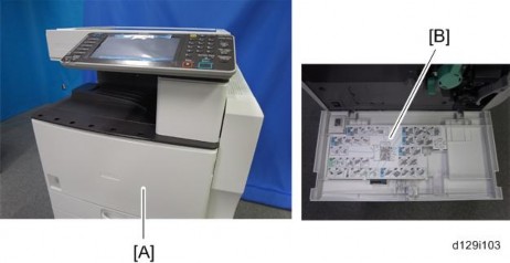
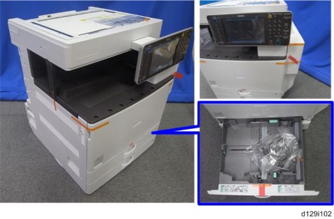
For installing the tray heater in the D580 (Two-tray paper feed unit)
Pull out the two trays from the optional paper feed unit.

Install the tray heater [1] in the optional paper feed unit ![]() x 1).
x 1).

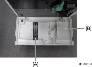
Remove the two securing brackets [2] ![]() x 1 each), and then the rear cover [3] of the optional paper feed unit
x 1 each), and then the rear cover [3] of the optional paper feed unit ![]() x 2).
x 2).

Connect the harness [4] to the connector [5] of the tray heater.
Route the harness [4] as shown and clamp it with four clamps ![]() x 4).
x 4).
Connect the harness [4] to the connector [6] of the mainframe.
Remove the connector cover [7] ( x 1).
7.

Release the optional heater relay connector [8] ![]() x 1).
x 1).
Connect the optional heater relay connector to the connector [9] (rear side) of the main frame ![]() x 1).
x 1).
Reassemble the mainframe and optional paper feed unit.
For installing the tray heater in the D581 (LCT)
Remove the rear cover of the mainframe ![]() x 6).
x 6).
Pull out the LCT drawer.
![]()
Installation
If the right tray comes out with the left tray, push the right tray into the LCT.

Left tray [1] ![]() x 2)
x 2)

Remove the right tray [2] while pressing down the stopper [3].
![]()
When reinstalling the right tray, set the right tray on the guide rail and carefully push the tray in, making sure to keep the tray level.
Install the tray heater [4] in the optional LCT ![]() x 1).
x 1).

Remove the two securing brackets [5] ![]() x 1 each), and then the rear cover [6] of the optional LCT
x 1 each), and then the rear cover [6] of the optional LCT ![]() x 2).
x 2).

Connect the harness [7] to the connector [8] of the tray heater.
Route the harness [7] as shown and clamp it with four clamps ![]() x 4).
x 4).
Connect the harness [7] to the connector [9] of the mainframe.
Reassemble the rear cover of the optional LCT.
Remove the connector cover [10] ( x 1).
Installation

Release the optional heater relay connector [11] ![]() x 1).
x 1).
Connect the optional heater relay connector to the connector [12] (rear side) of the main frame ![]() x 1).
x 1).
Reassemble the mainframe and optional LCT.
No. | Description | Q'ty |
1 | HDD Unit | 1 |
2 | Connecting Board Unit | 1 |
3 | Screw - M3 x 6 | 5 |
4 | Harness 1 | 1 |
5 | Harness 2 | 1 |

Installation

Remove the controller board unit [A] ![]() x 2).
x 2).

Connect the two harnesses to the HDD unit [A] ![]() x 2).
x 2).

Install the connecting board unit [A] on the HDD unit [B] ![]() x 2).
x 2).

Connect the two harnesses from the HDD unit to the connecting board [A] ![]() x 2).
x 2).

Install the HDD unit [A] on the controller board unit ![]() x 3).
x 3).
Reinstall the controller board unit in the machine.
After Installing the HDD
Do SP5832-001 to format the hard disk.
Do SP5853-001 to copy the preset stamp data from the firmware to the hard disk.
Do SP5846-040 to copy the address book to the hard disk from the controller board.
Do SP5846-041 to let the user get access to the address book.
Turn the main power switch off/on.
Installation
No. | Description | Q’ty | For this model |
1 | Bracket 1 | 1 | Yes |
2 | ICIB-3 | 1 | Yes |
3 | Flexible cable: Long | 1 | Not used |
4 | Flexible cable: Short | 1 | Not used |
5 | Harness with bands | 1 | Not used |
6 | Harness | 1 | Not used |
7 | Small Bracket | 1 | Not used |
8 | Saddle Clamp | 1 | Not used |
9 | Screws: M3x6 | 6 | Yes |
10 | Screws: M3x4 | 2 | Yes |
11 | Bracket 2 | 1 | Not used |

![]()
Unplug the main machine power cord before you do the following procedure.
Rear cover ![]() p.4-4)
p.4-4)
Controller unit ![]() p.4-95)
p.4-95)
Controller box ![]() p.4-101 "Mother Board")
p.4-101 "Mother Board")

Attach bracket 1 [A] to the ICIB-3 [B] ![]() x 2; M3 x 4).
x 2; M3 x 4).

Installation
Connect the ICIB-3 with bracket 1 [A] to CN 505 on the IPU ![]() x 2; M3 x 6).
x 2; M3 x 6).
Reassemble the machine.
User Tool Setting
Plug in and turn on the main power switch.
Go into the User Tools mode, and select System Settings > Administrator Tools > Data Security for Copying > "On".
Exit the User Tools.
Check the operation.
![]()
The machine will issue an SC165 error if the machine is powered on with the ICIB-1 removed and the "Data Security for Copying" feature is set to "ON".
When you remove this option from the machine, first set the setting to "OFF" with the user tool before removing this board. If you forget to do this, "Data Security for Copying" feature cannot appear in the user tool settings. And then SC165 will appear every time the machine is switched on, and the machine cannot be used.
Check All Connections
Make sure that the machine can recognize the option.
Plug in the power cord.
Turn on the main switch.
Enter the printer user mode. Then print the configuration page. User Tools > Printer Features > List Test Print > Configuration Page
All installed options are shown sin the "System Reference" column.
2.22 BROWSER UNIT TYPE I
Use the following procedure to install the Browser Unit Type I.
Installation
Turn the main switch ON.
Press the “User Tools/Counter” key.
On the touch panel, press “System Settings”.
Make sure that the “Increase Scanner Memory by Disabling Browser” setting in the General Features tab is OFF.
Turn the main switch OFF.
Remove the control cover [A] (screws x 2).
Insert the Browser Option SD card in the lower slot [A].
Turn the main switch ON.
Touch the “User Tools/Counter” key.
On the touch panel, touch “Extended Feature settings”.
Touch “Extended Feature settings” in the Extended Feature Settings Menu.
Make sure that “Extended JS” application was automatically installed in the Startup Settings tab.
Turn the main switch OFF/ON.
Move the application to the SD card that is installed to slot 1.
Note: See the Service Manual for details on merging SD Applications.
Press the “User Tools/Counter” key.
Installation
Touch “Edit home”.
Touch “Add Icon”.
Touch “Browse”.
Touch a blank square to set the location for the browser icon.
Touch “Exit” to complete the addition of the FAX browser icon.
Turn the main switch ON.
Press the “User Tools/Counter” key.
On the touch panel, touch “Browser Features”.
Touch “JavaScript”.
Change the Extended JavaScript setting to “Active”.
Note:
The firmware configuration of the Browser Unit Type I has been changed to enhance browsing.
Installation
The Browser Unit Type I consists of the Browser firmware and EXJS firmware. The EXJS firmware is equivalent to the existing browser firmware. Therefore, it is possible to update the EXJS firmware using the same procedure as that of SDK application firmware.
Both the Browser firmware and EXJS firmware are automatically installed when the Browser SD card is inserted in the upper slot.
Preparation:
Download the latest EXJS firmware from the RISSN server.
Extract the exe file (XXXX. exe), after which the following two files are generated: XXXX_machine. exe/ XXXX_stock.exe.
Note: The file (XXXX_machine) is for updating the EXJS firmware in the field.
Extract the file (XXXX_machine), after which the “SDK” folder is created.
Copy the “SDK” folder to an SD card.
Note: XXXX = part number.
Main procedure:
Remove the control cover [A] (screws x 2).
Insert the SD card included for firmware update into the lower slot [A].
Turn the main switch ON.
After the Update screen is displayed, select the “Browser”.
Touch “Update (#)”.
After the "Update Done" message appears on the screen, turn the main power switch OFF.
Remove the SD card from the lower slot.
Do the following steps if you are updating the Extended JavaScript.
Turn the main switch ON.
Press the “User Tools/Counter” key.
On the touch panel, touch “Extended Feature settings”.
Touch “Extended Feature settings” in the Extended Feature Settings Menu.
Change the status of “Extended JS” to “Ending” in the Startup Settings tab.
Turn the main switch OFF.
Insert the SD card containing the Extended JS firmware into the lower slot.
Turn the main switch ON.
Press the “User Tools/Counter” key.
On the touch panel, push “Extended Feature settings”.
Touch “Extended Feature settings” in the Extended Feature Settings Menu.
Installation
Touch the “Install” tab.
Touch “SD card”, then select “Extended JS” from the list of Extended Features.
Select “Machine HDD” as the “Install to” destination, then touch “Next”.
Check the Extended Features information on the “Ready to Install” screen, then press “OK”.
After “The following extended feature has already been installed. Are you sure you want to overwrite it?” is displayed, press “Yes”.
Change the status of Extended JS to “waiting” in the Startup Settings tab.
Turn the main switch OFF.
Remove the SD card from slot 2 (lower slot).
Turn the main switch ON.
Press the “User Tools/Counter” key.
On the touch panel, touch “Extended Feature settings”.
Touch “Extended Feature settings” in the Extended Feature settings Menu.
Make sure that the “Extended JS” has been updated to the latest version in the Startup Settings tab.
Turn the main switch ON.
Press the “User Tools/Counter” key.
Login with an administrator user name and password.
On the touch panel, touch “Extended Feature settings”.
Touch “Extended Feature settings” in the Extended Feature Settings Menu.
Touch “Extended Feature settings” in the Extended Feature Settings Menu.
Installation
Touch “Uninstall”.
Touch “Browser”, and then touch “Yes” after “Are you sure you want to uninstall the following extended feature?” is displayed.
Note: “Uninstalling the extended feature... Please wait” is then displayed on the touch screen.
After "Completed" is displayed, turn the main power switch OFF
Note: The Browser firmware is un-installed from the machine when the Browser SD card is removed.
Card Reader Bracket Type C3352 (D593)
Rev. 04/20/2012
Check the quantity and condition of the accessories against the following list.
No | Description | Q'ty | For This Model |
1 | Screw: M3 x 8 | 5 | Yes |
2 | Screw: M3 x 14 | 1 | Not used |
3 | Screw: M4 x 25 | 1 | Not used |
4 | Tapping Screw: M3 x 10 | 3 | Yes |
5 | Upper Tray | 1 | Yes |
6 | Lower Tray | 1 | Yes |
7 | Tray Bracket | 1 | Yes |

Rev. 04/20/2012
Card Reader Bracket Type C3352 (D593)
Installation

Attach the tray bracket [A] to the scanner right cover ![]() [B] x 2: M3x 8
[B] x 2: M3x 8
For this model, use the screw holes marked "1" on the table bracket.

Attach the lower tray [A] to the tray bracket ![]() x 2: M3x8).
x 2: M3x8).
Attach the upper tray [B] to the tray bracket ![]() x 1: M3x8).
x 1: M3x8).
Connect the cable to the designated connector (the connector to use depends on the type of device to be connected).
2.24 FAX CONNECTION UNIT TYPE A (D629-31) (REMOTE FAX)
This unit allows a machine without the FAX unit installed (“Client-side Machine”) to send and receive faxes via a machine with the FAX unit installed (“Remote Machine”).
Requirements:
Both the Client-side Machine and Remote Machine must have this unit, the Printer unit, and Scanner unit installed.
Up to six machines can be registered as the Client-side Machines.
Machines that have the FAX unit installed cannot be used as the Client-side Machine.
Only machine can be registered as the Remote Machine.
Firmware for this unit: “aics” (software number: D6295750)
Remote Fax transmissions are possible on a G3 line.
The remote fax function does not support User Code Authentication. Disable the User Code Authentication on the Remote machine.
Use this function to check the contents of a file that is stored in memory and not yet sent.
Also, use this function to cancel a transmission from the Client-side Machine.
![]()
Before installing this option:
Upgrade the machine firmware to the following versions or newer.
Firmware | P/N | Suffix | Ver. |
System/Copy | D1295751 | F | 2.00.3 |
Network Support | D1295754 | D | 11.77.2 |
Network DocBox | D1295757 | D | 2.01 |
Fax | D1295753 | D | 02.03.00 |
RemoteFax | D1295752 | D | 02.00.00 |
Websupport | D1295755 | D | 1.11 |
WebUapl | D1295756 | D | 1.04 |
JAVA (Standard) | D1295735 | C | 10.03.01 |
JAVA (Option) | D6405750 | G | 10.03.01 |
Scanner | D1295759 | C | 01.11 |
Printer | D1295763 | C | 1.06 |
PCL | D1295762 | C | 1.08 |
FCU | D6295570 | C | 02.00.00 |
Installation
On both the Remote Machine and the Client-side Machines:
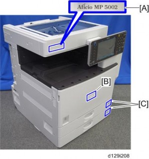
Remove the SD-card slot cover [A] from the SD card slots (Screw x 1)
Insert the SD card (Fax Connection Unit Type A) in SD slot 2 (lower) with its label face [B] towards the front of the machine. Then push it slowly into SD slot 2 (lower) until you hear a click.
Plug in, and then turn on the machine.
Move the Fax Connection Unit Type A application from the SD card in SD slot 2 (lower) to the SD card in SD slot 1 (upper) with SP5-873-001.
Turn off the machine.
Remove the SD card from SD slot 2 (lower), and then keep it in a safe place (see “SD Card Appli Move” in the manual for the main frame).
Attach the SD-card slot cover, and then turn on the machine (x 1)
Make sure that the machine can recognize the option (see ‘Check All Connections’ in the controller option section of the manual for the main frame)
Only one machine can be registered as the Remote Machine.
On the Client-side Machine(s):
Press the [User Tools/Counter] key on the operation panel
Press [System Settings > Administrator Tools] to select.
Press [Program/Delete Remote Machine] to select.
Enter the IP address or host name of the Remote Machine.
Press [Set] to set after “connection test”.
Press [Exit] to exit from the set-up procedure.
Up to six machines can be registered as the Client-side Machines.
On the Remote Machine:
Press the [User Tools/Counter] key on the operation panel
Press [Administrator Tools] to select.
Press [Program/Delete Remote Machine] to select.
Enter the IP address or host name of the Client-side Machines.
Press [Set] to set after “connection test”.
Do the following procedure to enable the Client-side Machine(s) to receive faxes via the Remote Machine. You can forward or route received documents per line or special sender or box.
Installation
By performing procedures #1-3 above, the Client-side Machines can send faxes via the Remote Machine. The procedures shown below are necessary to enable the
Client-side Machines to receive faxes.
On the Remote Machine:
If you use "Remote Reception Setting per Line"
Press [Facsimile Features] to select.
Press [Remote Reception Setting per Line] in [Reception Settings] to select.
Enter an IP address or a host name of the client-side machine to connect.
Press [Set], and [Exit] to exit from the setting.
If you use "Remote Reception per Sender"
Press [Facsimile Features] to select.
Press [Program Special Sender] in [Reception Settings] to select.
Select the Special Sender.
Press [Remote Reception Setting per Sender] to select.
Press [On] and [Remote Machine] to select.
Enter an IP address or a host name of the client-side machine to connect.
Press [OK] to exit from the setting.
If you use "Remote Reception per Box"
Press [Facsimile Features] to select.
allation Inst
Press [Box Setting] in [General Settings] to select.
Select the box.
Press [Personal Box] to select.
Enter a dial-in number.
Press [Remote Machine] to select.
Enter an IP address or a host name of the client-side machine to connect.
Press [OK] to exit from the set-up procedure.
This procedure allows the remote fax icon to appear on the home screen of the operation panel.
On both the Remote Machine and the Client-side Machines:
Installation
Press [User Tools].
Press [Edit Home].
Press [Add Icon].
Press [Remote Fax].
Press a [Blank] to set a location for the remote fax icon.
Press [Exit] to exit from the set-up procedure.
RE V IS ION H IST ORY | ||
Page | Date | Added/ Updated/ New |
None | ||
PM Tables
See "Appendices" for the following information:
Preventive Maintenance
PM Tables
REVISION HISTORY | ||
Page | Date | Added/ Updated/ New |
6 13 | 09/11/2012 | Updated Operation Panel including LCD |
108 ~ 117 | 12/27/2012 | NVRAM on the BCU board |
108 | 1/4/2013 | NVRAM on the BCU board |
116 | 05/16/2012 | Touch Screen Calibration |
![]()
To avoid damage to the transfer belt, drum, or development unit when it is removed or re-installed, never turn off power switch while electrical components are active.
![]()
Turn off the main power switch and unplug the machine before attempting any of the procedures in this section.
Replacement and Adjustment
Do not loosen the screws that secure the LD drive board to the laser diode casing. Doing so would throw the LD unit out of adjustment.
Do not adjust the variable resistors on the LD unit, as they are adjusted in the factory.
The polygon mirror and F-theta lenses are very sensitive to dust. Do not open the optical housing unit.
Do not touch the glass surface of the polygon mirror motor unit with bare hands.
After replacing the LD unit, do the laser beam pitch adjustment.
Dispose of used toner in accordance with local regulations. Never throw toner into an open flame, for toner dust may ignite.
Part Number | Description | Q’ty |
A0069104 | Scanner Positioning Pin (4 pc./set) | 1 |
A2929500 | Test Chart – S5S (10 pc./set) | 1 |
A2309003 | Adjustment Cam – Laser Unit | 1 |
A2309004 | Positioning Pin – Laser Unit | 1 |
B6455010 | SD Card | 1 |
G0219350 | Loop Back Connector | 1 |
Part Number | Description | Q’ty |
A2579300 | Grease Barrierta S552R | 1 |
52039502 | Silicone Grease G-501 | 1 |
Left Cover ![]() p.4-4)
p.4-4)

Replacement and Adjustment
Open and remove the front door [A] (pin x 2).
Upper Inner Cover
Open the front door [A].
Upper inner cover [B] ![]() x 2)
x 2)
Lower Inner Cover
Remove the front door [A] (pin x 2)
Shield glass cover [C]
Shield glass [D] ![]() x 2)
x 2)
Lower inner cover [E]
1. Left cover [A] ( x 6)

1. Rear cover [A] ![]() x 6)
x 6)
Rear ![]() p.4-4)
p.4-4)

Replacement and Adjustment
Open the right door [A].
Scanner right cover [B] ![]() x 2)
x 2)
Right top cover [C] ![]() x 1)
x 1)
Right rear cover [D] ![]() x 4)
x 4)
1. Open the right door [A].
Front right cover [A] ( x 1)
2.
4.3.6 OPERATION PANEL
Front right cover ( p.4-6 "Front Right Cover")
Position the operation panel [A] as shown above.
Operation panel connector upper cover [B] ( x 1)
Position the operation panel [A] as shown above.
Remove the operation panel connector lower cover [B].
Remove the Scanner Left Cover ( Scanner Panels 4.4.2).
Remove the Scanner Right Cover ( Scanner Panels 4.4.2).
Remove the Scanner Front Cover ( Scanner Panels 4.4.2).
Replacement and Adjustment
Remove the Grounding Line [A].
[A]

Operation panel [A] ( x 4, x 3)
LCD
Remove the operation panel cover ( 4.3.6.
Remove the rear cover [A] ( x 6).
[A]
Remove the rear cover [B] together with the hinge [C] ( x 7).
[B]
[C]
Remove the three cables [D].
[D]
Important
There are two types of LCDs that use the same part number (D1291420), labeled Type A and Type B below. They are completely interchangeable (0.
Remove the LCDC [E] ( x 6, x 5).
Remove the bracket [F] ( x 9).
Remove the LCD.
Part
number
Description
Type A
Type B
D1291420
LCD:TFT: WVGA: LED:MV
However, the harnesses are connected in slightly different locations on the board. Make sure to connect the harnesses in the correct position, depending on the type of LCD. Harness connectors and screws are circled in red for both types.
Replacement and Adjustment
Replacing TYPE A:
[E]
[F]
Replacing TYPE B:
[E]
[F]
Front right cover ( p.4-6)
Paper exit cover [A] ( x 1)