![]()
Never install telephone wiring during a lightning storm.
Never install telephone jacks in wet locations unless the jack is specifically designed for wet locations.
Never touch uninsulated telephone wires or terminals unless the telephone line has been disconnected at the network interface.
Use caution when installing or modifying telephone lines.
Avoid using a telephone (other than a cordless type) during an electrical storm. There may be a remote risk of electric shock from lightning.
Do not use a telephone or cellular phone to report a gas leak in the vicinity of the leak.
![]()
Before installing the fax unit, switch off the main switch, and disconnect the power cord.
The fax unit contains a lithium battery. The danger of explosion exists if a battery of this type is incorrectly replaced. Replace only with the same or an equivalent type recommended by the manufacturer. Discard batteries in accordance with the manufacturer's instructions and local regulations.
![]()
Note for Australia:
Unit must be connected to Telecommunication Network through a line cord which meets the requirements of ACA Technical Standard TS008.
This manual uses several symbols.
![]()
: See or Refer to
![]()
: Screws
![]()
: Connector
![]()
: Clip ring
![]()
: E-ring
![]()
: Clamp

The following headings provide special information:
![]()
Failure to obey warning information could result in serious injury or death.
![]()
Obey these guidelines to ensure safe operation and prevent minor injuries.
![]()
Obey these guidelines to avoid problems such as misfeeds, damage to originals, loss of valuable data and to prevent damage to the machine.
![]()
This information provides tips and advice about how to best service the machine.
This section describes the installation procedures for printer, scanner, and other options for D129/D130 series machines.
Printer Scanner Unit Type 5002 (D641)
No. | Item | Merge Options |
D641 | Printer/Scanner Unit Type 5002 | - |
D641 | Printer Unit Type 5002 | Scanner Enhance Option |
D641 | Scanner Enhance Option Type 5002 | - |
No. | Item | Slots |
D377 | File Format Converter Type E | Board Slot. Only one of these boards can be installed at one time. |
G874 | Gigabit Ethernet Board Type A | |
D377 | IEEE 802.11a/g Interface Unit Type J -or- IEEE 802.11g Interface Unit Type K | |
B679 | IEEE 1284 Interface Board Type A | |
D566 | Bluetooth Interface Unit Type D | USB slot |
D641 | PostScript3 Unit Type 5002 | SD Card Slot 1 (Upper Slot) |
D641 | IPDS Unit Type 5002 | SD Card Slot 1 (Upper Slot) |
D640 | Browser Unit Type I | SD Card Slot 1 (Upper Slot) (Install, then remove) |
D640 | VM Card Type U | SD Card Slot 2 |
D629 | SD card for NetWare printing Type K | SD Card Slot 1 (Upper Slot) |
D594 | Memory Unit Type L 512MB | Controller Board |
![]()
If more than one SD card application is required, the applications must be moved to one SD card with SP5873-1. For more details about merging applications from SD card Slot 2 (Lower Slot) to Slot 1 (Upper Slot), see "Scanner Enhance Option" in this chapter.
The machine controller box has one board slot and two SD card slots.
Only one interface board option can be installed.
Only two SD cards are available for applications and maintenance.

Printer Scanner Unit Type 5002 (D641)
Board Slots
No. | Name | Description |
1 | USB-A | Both USB slots are used for the Bluetooth option and a card authentication device. |
2 | USB-B | Built-in for connection of USB devices (USB 2.0) |
3 | SD Card Slot 1 (Upper Slot) | For options provided on SD cards. The application SD card (with the exception of the VM card) can be installed in Slot 1 (Upper Slot). If two or more applications are to be used, move the applications to the same SD card with SP5873. |
4 | SD Card Slot 2 (Lower Slot) | For options provided on SD cards and servicing. The VM card must be installed in Slot 2 (Lower Slot). |
No. | Name | Description |
5 | Ethernet | Standard LAN connection point. 100BASE-TX/10BASE-T LAN |
6 | ISDN | Jack for ISDN connection (Japan Only) |
7 | Line 3 | Jack for a 3rd line connection to the Fax Interface Unit (D596) (G3) when this option is installed. |
8 | Line 1 | Jack for the main telephone line from the outside for connection to Fax Option (D596). |
9 | TEL1 | Jack for telephone connection |
10 | Line 2 | Jack for a 2nd line connection to the Fax Interface Unit (D596) (G3) when this option is installed. |
11 | Board Slot | Optional interface boards are installed here. |
Orange LED: Lights when the network is connected and operating.
Green LED: Lights when 10BASE-TX or 100BASE-TX is operating.
Only two SD Card slots are available for applications.
To install more applications, they must be moved onto one SD Card.
The following optional interface boards are available. There is only one board slot so only one can be installed.
No. | Interface Board |
D377 | File Format Converter Type E |
G874 | Gigabit Ethernet Board Type A |
D377 | IEEE 802.11a/g Interface Unit Type J -or- IEEE 802.11g Interface Unit Type K |
B679 | IEEE 1284 Interface Board Type A |
![]()
Printer Scanner Unit Type 5002 (D641)
Only one of these boards can be installed at one time.
The following options are provided on SD cards.
Two SD card slots are available.
The VM application SD card must be installed in Slot 2 (Lower Slot).
Other applications should be installed in Slot 1 (Upper Slot). If more than one application is required, applications can be moved onto one SD card with SP5873-1.
No. | SD Card Applications |
D641 | PostScript3 Unit Type 5002 |
D641 | IPDS Unit Type 5002 |
D640 | Browser Unit Type I |
D629 | SD card for NetWare printing Type K |
D641 | Printer/Scanner Unit Type 5002 |
D641 | Printer Unit Type 5002 |
D641 | Scanner Enhance Option Type 5002 |
The following option is provided on a USB Device.
No. | USB Device |
D566 | Bluetooth Interface Unit Type D |
This section describes the installation of the following items:
Printer Unit
Printer/Scanner Unit
512 Memory. Optional memory is required for each unit. (Included in the Printer Unit or P/S Unit for NA models)
Printer Scanner Unit Type 5002 (D641)
Scanner Enhance Option

Printer Unit Type 5002:
For customers who do not require the extended scanning features but need more printing capability (PCL printer languages are provided). The 512 MB memory is required.
Printer/Scanner Unit Type 5002:
For customers who require the full range of DS features (advanced scanning and printing features such as "scan-to" solutions, virtual mailboxes, PCL, etc.). The 512 MB memory unit is required.
There are two separate options: 512 MB memory and PS3.
512 MB memory:
Every unit (Printer Unit, P/S unit) requires installation of the 512 MB memory.
PostScript 3 Unit:
The PS3 option can be used with the Printer Unit, or the Printer/Scanner Unit.
Scanner Enhance Option Type 5002 updates the Printer Unit by adding the advanced scanning features.
Check the accessories and their quantities against the list below and the illustration on the next page. This is a common list for all the kits.
This common accessory table lists all the items of the following units.
PU: Printer Unit
P/S: Printer/Scanner Unit
SEO: Scanner Enhance Unit
No. | Description | Q'ty | Kit Contents | ||
PU | P/S | SEO | |||
512 MB Memory*1 | - | No | No | No | |
1 | HDD Unit | 1 | Yes | Yes | No |
2 | Screw | 3 | Yes | Yes | No |
3 | SD Card | 1 | Yes | Yes | Yes |
*1: The 512 Memory is a separate option and it is not provided in the kits. However, one memory unit is required for the installation of every print unit. (Included in the Printer Unit or P/S Unit for NA models)
![]()
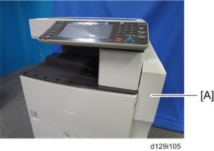
Turn off the main power switch and disconnect the power supply cord.
1. Remove the controller board [A] ( x 2).

Printer Scanner Unit Type 5002 (D641)
Connect the two harnesses to the HDD unit [A] ![]() x 2).
x 2).

Install the connecting board unit [A] on the HDD unit [B] ![]() x 2).
x 2).
Connect the two harnesses from the HDD unit to the connecting board [A] ![]() x 2).
x 2).

Install the HDD unit [A] on the controller board unit ![]() x3).
x3).

Install the 512 MB memory [A].
Reinstall the controller board.

Printer Scanner Unit Type 5002 (D641)
Remove the controller cover [A].

Insert the Printer/Scanner SD card in SD card Slot 1 (Upper Slot) [A].
Reattach the cover.

Attach the supplied ferrite core [A] at the machine end of the Ethernet cable.
Connect the Ethernet interface cable to the 10BASE-T/100BASE-TX port [A].
Connect the other end of the Ethernet interface cable to a network connection device such as a hub.
Connect the machine’s power cord and turn the main power switch on.
Enable the NIB and/or USB function.
To enable the NIB function, enter the SP mode and set SP5985-001 (On Board NIC) to "1" (Enable).
To enable the USB function, enter the SP mode and set SP5985-002 (On Board USB) to “1" (Enable).
Refer to the "Common Accessory Table" in this chapter.
The installation of the scanner enhance option are done with SP5873-001 (Application Move).
![]()
If you are going to update the RPCS unit with both the printer and scanner enhance options, the order of execution is not important.
Turn off the copier.
Remove the cover ![]() x1).
x1).
Confirm that the Printer Unit SD card is in SD card Slot 1 (Upper Slot).
Put the option SD Card (Scanner Enhance Option) in SD card Slot 2 (Lower Slot).
Open the front door.
Turn the copier on.
Go into the SP mode and select SP5873-001.
Touch "Execute".
Read the instructions on the display and touch "Execute" to start.
When the display tells you copying is completed, touch "Exit", then turn the copier off.
Remove the option SD card from Slot 2 (Lower Slot).
Turn the copier on.
Go into the User Tools mode and confirm that update was successful.
User Tools> System Settings> Administrator Tools> Firmware Version> Next
Turn the copier off again, then reattach the cover.
Return the copied SD card to the customer for safekeeping, or tape it to the faceplate of the controller.
Turn the main switch off.
Confirm that the Printer Unit SD card is in SD card Slot 1 (Upper Slot).
Put the original option SD card (Scanner Enhance Option) in SD card Slot 2 (Lower Slot).
Turn the main switch on.
Go into the SP mode and do SP5873-002 (Undo Exec).
Follow the messages on the operation panel to complete the procedure.
Printer Scanner Unit Type 5002 (D641)
Turn the main switch off.
Remove the option SD card from Slot 2 (Lower Slot).
Turn the main switch on.
Go into the User Tools mode and confirm that undo was successful.
User Tools> System Settings> Administrator Tools> Firmware Version> Next
Turn the copier off again, then reattach the cover.
Here are some basic rules about merging applications on SD cards.
The data necessary for authentication is transferred with the application program to the target SD card.
The SD card is the only evidence that the customer is licensed to use the application program. The service technician may occasionally need to check the SD card and its data to solve problems. SD cards must be stored in a safe location at the work site.
Once the merge is completed, the SD card from which the application was copied cannot be used again, but the customer must keep the card to serve as proof of purchase.
An SD card from which an application has been moved to another SD card can be restored to full operation with SP5873-002 (Undo).
Before storing the card from which an application has been copied, label it carefully so that you can identify it easily if you need to do the undo procedure later.
This machine has two SD card slots only. However, more than two optional applications are supplied for this machine. Always keep SD card Slot 2 (Lower Slot) vacant for servicing (except for the VM Card). Because of this, SD card merge is required if a customer wants to use many applications.
Consider the following limitations when you try to merge SD cards.
The destination SD card should have the largest memory size of all the application SD cards. Refer to the following table for the memory size of each SD card.
SD Card Options | SD Card Size |
Printer/Scanner Unit Type 5000 | 512 MB |
Printer Unit Type 5002 | 512 MB |
Scanner Enhance Option Type 5002 | 128 MB |
PostScript3 Unit Type 5000 | 512 MB |
IPDS Unit Type 5002 | 128 MB |
SD card for NetWare printing Type K | 128 MB |
Browser Unit Type I | 128 MB |
VM Card Type U | 512 MB |
Merge all applications which the customer wants to use into one SD card (Destination card inserted in Slot 1 (Upper Slot)).
Printer Scanner Unit Type 5002 (D641)
This machine has a board slot for optional I/F connection and two SD card slots for applications. After you install an option, check that the machine can recognize it. ![]() p.30 "Check All Connections")
p.30 "Check All Connections")

This slot [4] is used for one of the optional board connections (only one can be installed): IEEE1284, IEEE802.11a/g, g (Wireless LAN), Gigabit Ethernet, or File Format Converter.
PostScript3 Unit, IPDS Unit, Browser Unit, SD Card for Netware printing should be installed in Slot 1 (Upper Slot) [1].
VM Card must be installed in Slot 2 (Lower Slot) [2]. However, it can also be merged to the SD card in Slot 1 (Upper Slot).
Bluetooth Interface Unit is installed in the USB slot [3].
![]()
Unplug the main machine power cord before you do the following procedure.
1. Remove the controller cover [A] ( x 2)

Turn the SD-card label face to the rear of the machine. Then push it slowly into Slot 1 (Upper Slot) [A] until you hear a click.
Attach the controller cover ![]() x 2).
x 2).

Attach the "Adobe PostScript 3" decal [A] to the front door.
Make sure that the machine can recognize the option. ![]() p.30 "Check All Connections")
p.30 "Check All Connections")
![]()
Unplug the main machine power cord before you do the following procedure.

Printer Scanner Unit Type 5002 (D641)
Remove the slot cover [A] from the board slot ![]() x 2).
x 2).
Install the file format converter into the board slot, and then fasten it with screws.
Plug in and turn on the main power switch.
Check or set the following SP codes with the values shown below.
SP No. | Title | Setting |
SP5-836-001 | Capture Function (0:Off 1:On) | "1" |
SP5-836-002 | Panel Setting | "0" |
Check the operation.
Make sure that the machine can recognize the option. ![]() p.30 "Check All Connections")
p.30 "Check All Connections")
![]()
Unplug the main machine power cord before you do the following procedure.
You can only install one of the following network interfaces at one time: (IEEE 802.11a/g, g (Wireless LAN), IEEE1284, Bluetooth).

Remove the slot cover [A] from the board slot ![]() x 2).
x 2).
Install the interface board (Knob-screw x 2) into the board slot.
Make sure that the machine can recognize the option. ![]() p.30 "Check All Connections")
p.30 "Check All Connections")
![]()
Unplug the main machine power cord before you do the following procedure.
You can only install one of the following network interfaces at one time: (IEEE 802.11a/g, g (Wireless LAN), IEEE1284, Bluetooth).

Printer Scanner Unit Type 5002 (D641)
Remove the slot cover [A] from the board slot ![]() x 2).
x 2).
Install the wireless LAN board (Knob-screw x 2) into the board slot.
Make sure that the machine can recognize the option. ![]() p.30 "Check All Connections")
p.30 "Check All Connections")

Peel off the double-sided tapes on the Velcro fasteners [A], and then attach them [B] at the front left and rear right of the machine.
Attach the "ANT1" (having a black ferrite core) to the front left of the machine.
Attach the "ANT2" (having a white ferrite core) to the rear right of the machine.
![]()
"ANT1" is a transmission/reception antenna and "ANT2" is a reception antenna. Do not attach them at the wrong places.
Attach the clamps as shown above.
Wire the cables and clamp them ![]() x 8).
x 8).
![]()
Make sure that the cables are not slack. Keep them wired tightly along the covers. You may have to move the machine if the reception is not clear.
Make sure that the machine is not located near an appliance or any type of equipment that generates strong magnetic fields.
Put the machine as close as possible to the access point.
Go into the User Tools mode and do the procedure below. These settings take effect every time the machine is powered on.
![]()
You cannot use IEEE 802.11a/g if you use Ethernet.
Press the “User Tools” key.
On the touch panel, touch “System Settings”.
![]()
Select “Interface Settings”> “Network” > “LAN Type”. The “LAN Type” (default: Ethernet) must be set for either Ethernet or wireless LAN.
Select “Interface Settings”> “Wireless LAN”. Only the wireless LAN options show.
Set the “Communication Mode“.
Enter the “SSID setting”. (The setting is case sensitive.)
Set the “Ad-hoc Channel”. You need this setting when Ad Hoc Mode is selected. The allowed range for the channel settings may vary for different countries.
Region A (mainly Europe and Asia)
Range: 1-13, 36, 40, 44 and 48 channels (default: 11)
![]()
In some countries, only the following channels are available:
Range: 1-11 channels (default: 11)
Region B (mainly North America)
Range: 1-11, 36, 40, 44 and 48 channels (default: 11)
Set the “Security Method” to specify the encryption of the Wireless LAN.
The “WEP” (Wired Equivalent Privacy) setting is designed to protect wireless data transmission. The same WEP key is required on the receiving side in order to unlock encoded data. There are 64 bit and 128 bit WEP keys.
Range of Allowed Settings: 64 bit: 10 characters
128 bit: 26 characters
Specify “WPA” when “Communication Mode” is set to “Infrastructure Mode”. Set the “WPA Encryption Method” and “WPA Authent. Method”.
WPA Encryption Method:
Printer Scanner Unit Type 5002 (D641)
Select either "TKIP" or "CCMP (AES)".
WPA Authent. Method:
Select either “WPA-PSK”, “WPA”, “WPA2-PSK", or “WPA2”.
If you select “WPA-PSK” or “WPA2-PSK”, enter the pre-shared key (PSK) of 8 - 63 characters in ASCII code.
When “WPA” or “WPA2” are selected, authentication settings and certificate installation settings are required.
Press “Wireless LAN Signal” to check the machine's radio wave status using the operation panel.
Press “Restore Factory Defaults” to initialize the wireless LAN settings. Press “Yes” to initialize the following settings:
Transmission mode
Channel
Transmission Speed
WEP
SSID
WEP Key
The following SP commands and UP modes can be set for IEEE 802.11
SP No. | Name | Function |
5840 006 | Channel MAX | Sets the maximum range of the channel settings for the country. |
5840 007 | Channel MIN | Sets the minimum range of the channels settings allowed for your country. |
5840 008 | Transmission Speed | Sets the transmission speed. Auto, 54 Mbps, 48 Mbps, 36 Mbps, 24 Mbps, 18 Mbps, 12 Mbps, 9 Mbps, 6 Mbps, 11 Mbps, 5.5 Mbps, 2 Mbps, 1 Mbps (default: Auto). |
5840 011 | WEP Key Select | Used to select the WEP key (Default: 00). |
UP mode | Name | Function |
SSID | Used to confirm the current SSID setting. | |
WEP Key | Used to confirm the current WEP key setting. | |
WEP Mode | Used to show the maximum length of the string that can be used for the WEP Key entry. | |
WPA Encryption Method | Used to confirm the current WPA encryption setting. | |
WPA Authent. Method | Used to confirm the current WPA authentication setting and pre-shared key. |
![]()
Turn off the main power switch and disconnect the power supply cord.

Printer Scanner Unit Type 5002 (D641)
Insert the Bluetooth unit into the USB-A slot [A].
Make sure that the machine can recognize the option. ![]() p.30 "Check All Connections")
p.30 "Check All Connections")
![]()
Bluetooth Unit and IEEE 802.11a/g or g Interface Unit cannot be set at the same time.
![]()
Unplug the main machine power cord before you do the following procedure.
You can only install one of the following network interfaces at one time: (IEEE 802.11a/g, g (Wireless LAN), IEEE1284, IEEE1394, Bluetooth).

Remove the slot cover [A] from the board slot ![]() x 2).
x 2).
Insert the Gigabit Ethernet Board into the I/F slot and fasten it with the screws.
Print a configuration page to confirm that the machine recognizes the installed board for USB2.0:
User Tools > Printer Features > List/Test Print > Configuration Page
Check the accessories and their quantities against the table below.
No. | Description | Q'ty |
1 | IPDS Emulation SD Card | 1 |
2 | Decal | 1 |
![]()
Printer Scanner Unit Type 5002 (D641)
Only two slots are available for SD cards that contain applications. If you want to use more than two applications, merge all applications into two SD cards (SP5873-001).
Check the software version.
If necessary, update the firmware to the required version.
Turn off the main switch.
Remove the controller cover [A] ( x 2)
4.

Insert the IPDS SD Card into Slot 1 (Upper Slot) [A].
![]()
Pushing in the SD Card releases it for removal. Make sure the SD Card is inserted and locked in place. If it is partially out of the slot, push it in gently until it locks in place.
Reattach the controller cover and turn ON the main switch.
Do one of the following ("A" or "B") to enable the IPDS function.
[Enable the IPDS function via telnet]
Connect the machine via telnet.
Execute the following commands: msh> set ipds up
***If you want to stop the function. msh> set ipds down
[Enable the IPDS option via WebImageMonitor]
Log in to WebImageMonitor.
Change the setting to enable IPDS.

Printer Scanner Unit Type 5002 (D641)
Attach the decal [A] as shown in the photo above.
Line up the left side of the decal with the left edged of the main power switch. ([B]: 10 mm or more)
This option is only for basic models.
Check the accessories and their quantities against the table below.
Description | Q'ty |
1. VM SD Card | 1 |
2. Decal | 1 |
Printer Scanner Unit Type 5002 (D641)
1. Switch the machine off.
Remove the controller cover [A] ( x 2)
2.
Insert the SD card into SD Slot 2 (Lower Slot) [A].
![]()
This SD card must be inserted into Slot 2 (Lower Slot).
Plug in the power cord. Then turn on the main switch.
Enter the printer user mode. Then print the configuration page. User Tools > Printer Features > List Test Print > Configuration Page All installed options are shown in the “System Reference” column.
Printer Scanner Unit Type 5002 (D641)
1001 | Bit Switch | |||
001 | Bit Switch 1 | 0 | 1 | |
bit 0 | DFU | - | - | |
bit 1 | DFU | - | - | |
bit 2 | DFU | - | - | |
bit 3 | No I/O Timeout | 0: Disable | 1: Enable | |
Enable: The MFP I/O Timeout setting will have no effect. I/O Timeouts will never occur. | ||||
bit 4 | SD Card Save Mode | 0: Disable | 1: Enable | |
Enable: Print jobs will be saved to an SD Card in the GW SD slot. | ||||
bit 5 | DFU | - | - | |
bit 6 | DFU | - | - | |
bit 7 | [RPCS,PCL]: Printable area frame border | 0: Disable | 1: Enable | |
Enable: The machine prints all RPCS and PCL jobs with a border on the edges of the printable area. | ||||
1001 | Bit Switch | |||
002 | Bit Switch 2 | 0 | 1 | |
bit 0 | DFU | - | - | |
bit 1 | DFU | - | - | |
bit 2 | Applying a collation Type | Shift Collate | Normal Collate | |
A collation type (shift or normal) will be applied to all jobs that do not already have a ‘Collate Type’ configured.
| ||||
bit 3 | [PCL5e/c,PS]: PDL Auto Switching | 0: Enable | 1: Disable | |
Disable: The MFPs ability to change the PDL processor mid-job. Some host systems submit jobs that contain both PS and PCL5e/c. If Auto PDL switching is disabled, these jobs will not be printed properly. | ||||
bit 4 | DFU | - | - | |
bit 5 | DFU | - | - | |
bit 6 | DFU | - | - | |
bit 7 | DFU | - | - | |
If #5-0 is enabled, this Bit Switch has no effect.
Printer Scanner Unit Type 5002 (D641)
1001 | Bit Switch | |||
003 | Bit Switch 3 | 0 | 1 | |
bit 0 | DFU | - | - | |
bit 1 | DFU | - | - | |
bit 2 | [PCL5e/c]: Legacy HP compatibility | 0: Disable | 1: Enable | |
Enable: Uses the same left margin as older HP models such as HP4000/HP8000. In other words, the left margin defined in the job (usually "<ESC>*r0A") will be changed to "<ESC>*r1A" | ||||
bit 3 | DFU | - | - | |
bit 4 | DFU | - | - | |
bit 5 | DFU | - | - | |
bit 6 | DFU | - | - | |
bit 7 | DFU | - | - | |
1001 | Bit Switch | |||
004 | Bit Switch 4 | 0 | 1 | |
bit 0 | DFU | - | - | |
bit 1 | DFU | - | - | |
bit 2 | DFU | - | - | |
bit 3 | IPDS print-side reversal | 0: Disable | 1: Enable | |
Enable: Increases printing speed but simplex pages may be printed on the back side of the sheet. | ||||
bit 4 | DFU | - | - | |
bit 5 | DFU | - | - | |
bit 6 | DFU | - | - | |
bit 7 | DFU | - | - | |
Printer Scanner Unit Type 5002 (D641)
1001 | Bit Switch | |||
005 | Bit Switch 5 | 0 | 1 | |
bit 0 | Show "Collate Type", "Staple Type" and "Punch Type" buttons on the operation panel. | Disable | Enable | |
If enabled, users will be able to configure a Collate Type, Staple Type, and Punch Type from the operation panel. The available types will depend on the device and configured options. After enabling the function, the settings will appear under: "User Tools > Printer Features > System" | ||||
bit 1 | Multiple copies if a paper size or type mismatch occurs | 0: Disable (Single copy) | 1: Enable (Multiple copy) | |
If a paper size or type mismatch occurs during the printing of multiple copies, only a single copy is output by default. Using this Bit Switch, the device can be configured to print all copies even if a paper mismatch occurs. | ||||
bit 2 | DFU | - | - | |
bit 3 | [PS] PS Criteria | Pattern3 | Pattern1 | |
Change the number of PS criterion used by the PS interpreter to determine whether a job is PS data or not. Pattern3: includes most PS commands. Pattern1: A small number of PS tags and headers | ||||
bit 4 | Increase max number of the stored jobs to 1000 jobs. | Disable (100) | Enable (1000) | |
Enable: Changes the maximum number of jobs that can be stored on the HDD via Job Type settings to 1000. The default is 100. | ||||
bit 5 | DFU | - | - | |
bit 6 | Method for determining the image rotation for the edge to bind on. | 0: Disable | 1: Enable | |
If enabled, the image rotation will be performed as they were in the specifications of older models for the binding of pages of mixed orientation jobs. The old models are below: | ||||
bit 7 | Letterhead mode printing | 0: Disable | 1: Enable (Duplex) | |
Routes all pages through the duplex unit. If this is disabled, simplex pages or the last page of an odd-paged duplex job are not routed through the duplex unit. This could result in problems with letterhead/pre-printed pages. Only affects pages specified as Letterhead paper. | ||||
PCL: Pre-04A models
PS/PDF/RPCS:Pre-05S models
1001 | Bit Switch | ||
006 | Bit Switch 6 DFU | - | - |
1001 | Bit Switch | |||
007 | Bit Switch 7 | 0 | 1 | |
bit 0 | Print path | 0: Disable | 1: Enable | |
If enabled, simplex pages (in mixed simplex/duplex PS/PCL5 jobs only) and the last page of an odd paged duplex job (PS, PCL5, PCL6), are always routed through the duplex unit. Not having to switch paper paths increases the print speed slightly. | ||||
bit 1 to 7 | DFU | - | - | |
Printer Scanner Unit Type 5002 (D641)
1001 | Bit Switch | ||
008 | Bit Switch 8 DFU | - | - |
1001 | Bit Switch | |||
009 | Bit Switch 9 | 0 | 1 | |
bit 0 | PDL Auto Detection timeout of jobs submitted via USB or Parallel Port (IEEE 1284). | "Disabled (Immediately)" | "Enabled (10 seconds)" | |
To be used if PDL auto-detection fails. A failure of PDL autodetection doesn't necessarily mean that the job can't be printed. This bit switch tells the device whether to time-out immediately (default) upon failure or to wait 10 seconds. | ||||
bit 1 | DFU | - | - | |
bit 2 | Job Cancel | Disabled (Not cancelled) | Enabled (Cancelled) | |
If this bit switch, all jobs will be cancelled after a jam occurs. Note: If this bitsw is enabled, printing under the following conditions might result in problems: | ||||
bit 3 | PCL/PS bypass tray paper rotation (SEF/LEF) | 0: Disable | 1: Enable | |
This bitsw causes the device to revert to the behavior of previous generations. It only takes effect if "Bypass Tray Setting Priority" = "Driver/Command". Previous spec (bitsw=1): If a standard sized paper mismatch occurred in the bypass tray, the MFP always prompted for SEF paper. If this bitsw=0 (default) then in the event of a standard sized paper mismatch, the MFP will always prompt for paper of the rotation (SEF/LEF) determined by the MFP bypass tray paper setting or by the bypass tray sensor. | ||||
Job submission via USB or Parallel Port
Spool printing (WIM >Configuration > Device Settings > System)
bit 4 | Response to PJL USTATUS when multiple collated copies are printed | 0: Disable | 1: Enable | |
When enabled, if multiple collated copies are printed, the device no longer responds to PJL USTATUS with the number of pages in the current copy. Instead the device will return the total number of pages for all copies. | ||||
Bit 5 to 7 | DFU | - | - | |
1001 | Bit Switch | |||
010 | Bit Switch 10 | 0 | 1 | |
bit 0 to 4 | DFU | - | - | |
bit 5 | List / Test Print Lock | 0: Disable | 1: Enable | |
If enabled, you can lock or unlock the [List/Test Print] items under the Pinter Features menu when the Store and Skip Errored Job Function is on. | ||||
Bit 6 | Optional charge machines | - | - | |
If enabled, you can use the optional charge machines when the Store and Skip Errored Job Function is on. | 0: Disable | 1: Enable | ||
Bit 7 | DFU | - | - | |
Printer Scanner Unit Type 5002 (D641)
1001 | Bit Switch | |||
011 | Bit Switch 11 | 0 | 1 | |
bit 0 | List / Test Print menu | 0: Disable | 1: Enable | |
When enabled, [Multiple Lists] menu is displayed in [List / Test Print] under the Printer Features menu. | ||||
bit 1 | Interrupt printing | 0: Job | 1: Page | |
Selects the interrupting units for the interrupt printing function. When you select "0," you can interrupt printing of a job while being processed. When you select "1," you can interrupt printing of a page while being processed. | ||||
Bit 2 to 7 | DFU | - | - | |
1001 | Bit Switch | |||
012 | Bit Switch 12 | 0 | 1 | |
bit 0 to 7 | DFU | - | - | |
1003 | [Clear Setting] |
1003 001 | Initialize Printer System |
Initializes settings in the "System" menu of the user mode. | |
1003 003 | Delete Program |
1004 | [Print Summary] |
1004 001 | Print Printer Summary |
Prints the service summary sheet (a summary of all the controller settings). |
1006 | [Sample/Locked Print] | *CTL | 0: Link with Doc. Svr, 1: Enable |
1006 001 | Enables and disables the document server. When you select "0," the document server is enabled or disabled in accordance with Copy Service Mode SP5-967. When you select "1," the document server is enabled regardless of Copy Service Mode SP5-967. | ||
1110 | [Media Print Device Setting] | |
1110 002 | 0: Disable 1: Enable | Selects the setting for the media print device. |
1111 | [All Job Delete Mode] | |
1111 001 | 0: excluding New Job 1: including New Job | Select whether to include an image processing job in jobs subject to full cancellation from the SCS job list. |
Printer Scanner Unit Type 5002 (D641)
1005 | [Erase margin (Remote Scan)] | ||
Creates an erase margin for all edges of the scanned image. If the machine has scanned the edge of the original, create a margin. This SP is activated only when the machine uses TWAIN scanning. | |||
1005 1 | Range from 0 to 5 mm | *CTL | [0 to 5 / 0 / 1 mm/step ] |
1009 | [Remote scan disable] | *CTL | [0 or 1 / 0 / - ] 0: enable, 1: disable |
1009 1 | Enable or disable remote scan. | ||
1010 | [Non Display Clear Light PDF] | *CTL | [0 or 1 / 0 / - ] 0: Display, 1: No display |
1010 1 | Enable or disable remote scan. | ||
1011 | [Org Count Disp] | *CTL | [0 or 1 / 0 / - ] 0: No display, 1: Display |
1011 1 | This SP codes switches the original count display on/off. | ||
1012 | [User Info Release] | *CTL | [0 or 1 / 1 / - ] 0: Do not release, 1: Release |
1012 1 | This SP code sets the machine to release or not release the following items at job end. | ||
Destination (E-mail/Folder/CS)
Sender name
Mail Text
Subject line
File name
1013 | [Scan Media Device Setting] | *CTL | [0 or 1 / 1 / - ] 0: Disable, 1: Enable |
1013 1 | This SP code enables/disables the multi-media function option (USB 2.0/SD Slot) mounted on the left rear corner of the machine. Operators can scan documents to either an SD card or a USB memory device inserted into this unit. This SP must be enabled (set to "1") in order for the device to function. | ||
Printer Scanner Unit Type 5002 (D641)
2021 | [Compression Level (Gray-scale)] | ||
Selects the compression ratio for grayscale processing mode (JPEG) for the three settings that can be selected at the operation panel. | |||
2021 1 | Comp1: 5-95 | *CTL | [5 to 95 / 20 / 1 /step ] |
2021 2 | Comp2: 5-95 | [5 to 95 / 40 / 1 /step ] | |
2021 3 | Comp3: 5-95 | [5 to 95 / 65 / 1 /step ] | |
2021 4 | Comp4: 5-95 | [5 to 95 / 80 / 1 /step ] | |
2021 5 | Comp5: 5-95 | [5 to 95 / 95 / 1 /step ] | |
2024 | [Compression ratio of ClearLight PDF] | ||
Selects the compression ratio for clearlight PDF for the two settings that can be selected at the operation panel. | |||
2024 1 | Compression Ratio (Normal) | *CTL | [5 to 95 / 25 / 1 /step ] |
2024 2 | Compression Ratio (High) | [5 to 95 / 20 / 1 /step ] | |
2025 | [Compression ratio of ClearLight PDF JPEG2000] | ||
Selects the compression ratio for clearlight PDF for the two settings that can be selected at the operation panel. | |||
2025 1 | Compression Ratio (Normal) JPEG2000 | *CTL | [5 to 95 / 25 / 1 /step ] |
2025 2 | Compression Ratio (High) JEPG2000 | [5 to 95 / 20 / 1 /step ] | |
Printer Languages: | PCL 6/5e PDF Direct Adobe PostScript 3 (optional) IPDS (optional) MediaPrint: JPEG/TIFF (optional) |
Resolution and Gradation: | PCL 5e: 300 x 300 dpi 600 x 600 dpi : Fast (1-bit) PCL 6: 600 x 600 dpi : Fast (1-bit) PDF Direct: 300 x 300 dpi/600 x 600 dpi PS3: 300 x 300 dpi/600 x 600 dpi XPS: 600 x 600 dpi : Fast (1-bit) IPDS: 300 x 300 dpi/ 600 x 600 dpi |
Printing speed: | D129: 40 ppm D130: 50 ppm |
Resident Fonts: | PCL 6/5e (Standard): 45 Compatible fonts 13 International fonts 6 Bitmap fonts Adobe PostScript 3 (Optional): 136 fonts IPDS (Optional): 108 fonts |
Host Interfaces: | USB2.0 Type A and Type B: Standard Ethernet (100 Base-TX/10 Base-T): Standard Gigabit Ethernet (1000 Base-T): Optional IEEE1284 parallel x 1: Optional IEEE802.11a/b/g (Wireless LAN): Optional Bluetooth (USB type): Optional |
Network Protocols: | TCP/IP (IPv4, IPv6), IPX/SPX |
Printer Scanner Unit Type 5002 (D641)
USB connectivity is built into the controller.
Interface | USB 2.0 |
Data rates | 480 Mbps (high speed), 12 Mbps (full speed), 1.5 Mbps (low speed) High speed mode is only supported by USB 2.0. |
Standard applied | IEEE802.11a/b/g | |
Network protocols | TCP/IP, Apple Talk, NetBEUI, IPX/SPX, SMB | |
Frequency range | ||
(Center | | 2412 - 2462 MHz (1-11 channels) |
Frequency) | | 5180 - 5320 MHz (36, 40, 44, 48, 52, 56, 60, and 64 channels) |
(US model) | ||
Frequency range | ||
(Center | | 2412 - 2472 MHz (1-13 channels) |
Frequency) | | 5180 - 5320 MHz (36, 40, 44, 48, 52, 56, 60, and 64 channels) |
(EU model) | ||
Transmission Specifications | Based on Bluetooth Ver2.0+EDR |
Transmission Speed | |
Profile | Hard Copy Cable Replacement Profile (HCRP), Serial Port Profile (SPP), Basic Imaging Profile (BIP) |
Asynchronous Communication : Approximately 2.1 Mbps (Max)
Synchronous Communication : Approximately 1.3 Mbps (Max)
Printer Scanner Unit Type 5002 (D641)
Standard Scanner Resolution: | Main scan/Sub scan 200 to 600 dpi |
Available scanning Resolution Range: | Twain Mode: 100 to 1200 dpi Delivery Mode: 100/200/300/400/600 dpi |
Grayscales: | 1 bit or 8 bits/pixel each for RGB |
Scanning Throughput (ARDF mode): | BW: 61 ipm (A4LEF / BW Text/ Photo / 200dpi /Compression: On (MH)) FC: 31 ipm (A4LEF / FC Text / Photo / 200dpi / Compression: Standard) |
Interface: | Ethernet 10Base-T / 100Base-TX, Gigabit Ethernet (1000Base-T), Wireless LAN (IEEE 802.11a/b/g) |
Compression Method: | B&W: TIFF (MH, MR, MMR, JBIG2), Gray Scale Full Color: JPEG |
The printer drivers and utility software are provided on one CD-ROM. An auto-run installer allows you to select which components to install.
Printer Language | Windows XP, Server 2003, Server 2008, Vista, 7 | MacOSX10.2 or later |
PCL5c / PCL6 | Yes | No |
PS3 | Yes | Yes |
RPCS | No | No |
![]()
The PCL5c/6 and PS3 drivers are provided on the printer/scanner CD-ROM.
The PS3 drivers are all genuine Adobe PS drivers, except for Windows XP/Server 2003/Server 2008/Vista/7. A PPD file for each operating system is provided with the driver.
The PPD installer for Macintosh supports Mac OS X 10.2 or later versions.
Printer Language | Windows XP, Server 2003, Server 2008, Vista, 7 | MacOSX10.2 or later |
Network TWAIN | Yes | No |
LAN-FAX | Yes | No |
![]()
The Network TWAIN and LAN Fax drivers are provided on the printer and scanner drivers CD-ROM.
This software lets you fax documents directly from your PC. Address Book Editor and Cover Sheet Editor are to be installed as well. (These require the optional fax unit.)