R EVI SIO N HIS TORY | ||
Page | Date | Added/ Updated/ New |
None | ||
TRAYS AND COVERS 1
SUB AND MAIN OUTPUT TRAYS 1
TRAY LEFT FRONT AND REAR COVERS 2
ELECTRICAL COMPONENTS 3
SIDE TRAY CONTROL BOARD 3
SIDE TRAY DRIVE MOTOR 4
SIDE TRAY RELAY SENSOR 5
SIDE TRAY EXIT SENSOR 6
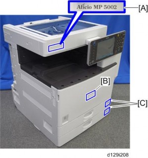
Trays and Covers

Sub output tray [A]
Release the rear tab of the sub output tray.
Main output tray [B]
Side Tray Type C5501/C5502 (D542/D635)
Release the rear tab of the sub output tray.
Trays and Covers
Sub and main output trays ![]() Sub and Main Output Trays)
Sub and Main Output Trays)

Tray left front cover [A]
Release the hooks of the tray left front cover.
Tray left rear cover [B]
Release the hooks of the tray left rear cover.
Electrical Components
Sub and main output trays ![]() Sub and Main Output Trays)
Sub and Main Output Trays)
Tray left front and rear covers ![]() Tray Left Front and Rear Covers)
Tray Left Front and Rear Covers)
Side tray ![]() Installation Procedure in the base copier manual)
Installation Procedure in the base copier manual)

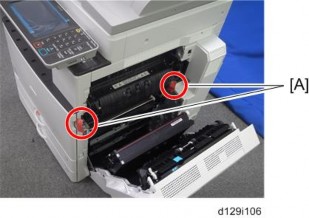
Rear cover [A] ![]() x 2)
x 2)

Side Tray Type C5501/C5502 (D542/D635)
Side tray control board [A] ![]() x 3,
x 3, ![]() x 3)
x 3)
Electrical Components
Sub and main output trays ![]() Sub and Main Output Trays)
Sub and Main Output Trays)
Tray left front and rear covers ![]() Tray Left Front and Rear Covers)
Tray Left Front and Rear Covers)
Side tray ![]() Installation Procedure in the base copier manual)
Installation Procedure in the base copier manual)
Rear cover ![]() Side Tray Control Board)
Side Tray Control Board)

Bracket [A] ![]() x 3,
x 3, ![]() x 3,
x 3, ![]() x 1, timing belt x 1)
x 1, timing belt x 1)

Side tray drive motor [A] ![]() x 4,
x 4, ![]() x 1)
x 1)
Electrical Components
Sub and main output trays ![]() Sub and Main Output Trays)
Sub and Main Output Trays)
Tray left front and rear covers ![]() Tray Left Front and Rear Covers)
Tray Left Front and Rear Covers)
Side tray ![]() Installation Procedure in the base copier manual)
Installation Procedure in the base copier manual)

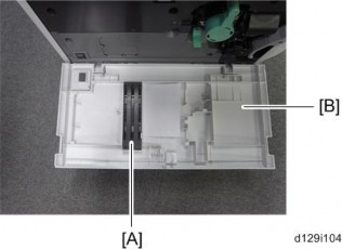
Open the paper tray [A].
Remove the ground cable [B] ![]() x 1).
x 1).
Remove the paper tray [A].
Turn over the side tray.

Side tray relay sensor [A] ![]() x 1, hooks)
x 1, hooks)
Side Tray Type C5501/C5502 (D542/D635)
Turn over the side tray, and then remove the side tray relay sensor.
Electrical Components
Sub and main output trays ![]() Sub and Main Output Trays)
Sub and Main Output Trays)
Tray left front and rear covers ![]() Tray Left Front and Rear Covers)
Tray Left Front and Rear Covers)
Side tray ![]() Installation Procedure in the base copier manual)
Installation Procedure in the base copier manual)
Paper tray ![]() Side Tray Relay Sensor)
Side Tray Relay Sensor)
Exit guide [A] ( x 1)
5.

6. Side tray exit sensor [A] ![]() x 1,
x 1, ![]() x 1, hooks)
x 1, hooks)
REVISION HISTORY | ||
Page | Date | Added/ Updated/ New |
3 4 | 11/15/2012 | Added step 6 to Installation for Fax Option (D629) |
FAX OPTION INSTALLATION 1
COMPONENT CHECK 1
FAX OPTION INSTALLATION PROCEDURE 2
G3 INTERFACE BOARD INSTALLATION 5
COMPONENT CHECK 5
INSTALLATION: ONE G3 BOARD 6
INSTALLATION: TWO G3 BOARDS 8
FAX UNIT OPTIONS 10
MEMORY UNIT (G578) 10
HANDSET (D645) 11
FCU 13
SRAM DATA TRANSFER PROCEDURE 13
ERROR CODES 19
IFAX TROUBLESHOOTING 41
IP-FAX TROUBLESHOOTING 44
IP-FAX TRANSMISSION 44
Cannot send by IP Address/Host Name 44
Cannot send via VoIP Gateway 46
Cannot send by Alias Fax number 47
IP-FAX RECEPTION 49
Cannot receive via IP Address/Host Name. 49
Cannot receive by VoIP Gateway 50
Cannot receive by Alias Fax number. 51
CAUTIONS 53
SERVICE PROGRAM TABLES 54
SP1-XXX (BIT SWITCHES) 54
SP2-XXX (RAM DATA) 55
SP3-XXX (TEL LINE SETTINGS) 57
SP4-XXX (ROM VERSIONS) 59
SP5-XXX (RAM CLEAR) 60
SP6-XXX (REPORTS) 61
SP7-XXX (TESTS) 64
BIT SWITCHES - 1 66
SYSTEM SWITCHES 66
BIT SWITCHES - 2 83
I-FAX SWITCHES 83
PRINTER SWITCHES 91
BIT SWITCHES - 3 99
COMMUNICATION SWITCHES 99
BIT SWITCHES - 4 110
G3 SWITCHES 110
BIT SWITCHES - 5 121
G3-2 AND G3-3 SWITCHES 121
G4 INTERNAL SWITCHES 130
G4 PARAMETER SWITCHES 130
BIT SWITCHES - 6 131
IP FAX SWITCHES 131
NCU PARAMETERS 140
DEDICATED TRANSMISSION PARAMETERS 155
PROGRAMMING PROCEDURE 155
PARAMETERS 156
Fax Parameters 156
E-mail Parameters 160
SERVICE RAM ADDRESSES 164
OVERVIEW 175
BOARDS 176
5.2.1 FCU 176
5.2.2 SG3 BOARD 178
VIDEO DATA PATH 180
TRANSMISSION 180
Memory Transmission and Parallel Memory Transmission 180
Immediate Transmission 181
JBIG Transmission 181
Adjustments 181
RECEPTION 182
FAX COMMUNICATION FEATURES 183
MULTI-PORT 183
DOCUMENT SERVER 184
INTERNET MAIL COMMUNICATION 185
Mail Transmission 185
Mail Reception 187
Handling Mail Reception Errors 189
Secure Internet Reception 190
Transfer Request: Request By Mail 190
E-Mail Options (Sub TX Mode) 191
IP-FAX 195
WHAT IS IP-FAX? 195
T.38 PACKET FORMAT 195
UDP Related Switches 195
SETTINGS 196
GENERAL SPECIFICATIONS 197
6.1.1 FCU 197
CAPABILITIES OF PROGRAMMABLE ITEMS 199
IFAX SPECIFICATIONS 201
IP-FAX SPECIFICATIONS 203
FAX UNIT CONFIGURATION 204
![]()
Never install telephone wiring during a lightning storm.
Never install telephone jacks in wet locations unless the jack is specifically designed for wet locations.
Never touch uninsulated telephone wires or terminals unless the telephone line has been disconnected at the network interface.
Use caution when installing or modifying telephone lines.
Avoid using a telephone (other than a cordless type) during an electrical storm. There may be a remote risk of electric shock from lightning.
Do not use a telephone or cellular phone to report a gas leak in the vicinity of the leak.
![]()
Before installing the fax unit, switch off the main switch, and disconnect the power cord.
The fax unit contains a lithium battery. The danger of explosion exists if a battery of this type is incorrectly replaced. Replace only with the same or an equivalent type recommended by the manufacturer. Discard batteries in accordance with the manufacturer's instructions and local regulations.
![]()
Note for Australia:
Unit must be connected to Telecommunication Network through a line cord which meets the requirements of ACA Technical Standard TS008.
This manual uses several symbols.
Symbol | What it means |
| Refer to section number |
| Screw |
| Connector |
| E-ring |
| Clip ring |
| Clamp |
The following headings provide special information:
![]()
Failure to obey warning information could result in serious injury or death.
![]()
Obey these guidelines to ensure safe operation and prevent minor injuries.
![]()
Obey these guidelines to avoid problems such as misfeeds, damage to originals, loss of valuable data and to prevent damage to the machine.
Always obey these guidelines to avoid serious problems such as misfeeds, damage to originals, loss of valuable data and to prevent damage to the machine. bold is added for emphasis.
![]()
This document provides tips and advice about how to best service the machine.
Fax Option Installation
Fax Option Type 5002 (D629)
Check the quantity and condition of the components against the following list.
No. | Description | Q'ty |
1 | FCU | 1 |
2 | Screw: M3x6 | 3 |
3 | Telephone Cable (NA only) | 1 |
4 | Data Display Decal Sheet (21 languages) (EU only) | 1 |
5 | FCC Decal (NA only) | 1 |
6 | Serial Number Decal | 1 |
7 | G3 Decal | 1 |
8 | EMC Address (EU only) | 1 |
9 | Fax Decal for Operation Panel | 1 |
Fax Option Installation

![]()
Before installation:
If there is a printer option in the machine, print out all data in the printer buffer.
Push the operation switch to put the machine in standby mode. Make sure the power LED is off, turn the main switch off, and then disconnect the power cord and the network cable.
The copier must be connected to a properly grounded socket outlet.
Attach the serial number decal near the serial number plate of the mainframe.
For NA models, attach the FCC decal near the serial number plate of the mainframe.
Remove the controller cover [A] ( x 2).
3.
Rev. 11/15/2012 Fax Option Installation
Fax Option Type 5002 (D629)
Remove the FCU cover [A] ( x 3).
Remove the jumper [A] (set to OFF) and set it to ON.
The machine may issue SC819, SC820 if the jumper is not set to "ON" correctly. (Sometimes these SC codes are not issued.)

The following step is for units installed in Brazil only!
For installation in Brazil, move the jumper switch (CN613) on the FAX board so that the edge is anchored at “1”. (So that the middle pin and the “1” pin are covered.)
In its default position, the switch covers the middle and “3” pin.

Install the FCU [A] ( x 4; use the three screws which were removed in step 3).
SM 3 D629
Fax Option Installation Rev. 11/15/2012

Reattach the controller cover [A] ( x2).
Connect the telephone cord to the "LINE 1" jack.

Attach the Super G3 decal [A].
Attach the Fax decal under the function key on the operation panel.
Plug in the machine and turn on the main power switch.
After you turn the machine on, if you see a message that tells you the SRAM has been formatted due to a problem with SRAM, turn the machine off and on again to clear the message.
Enter the "User Tools" mode and set date and time.
Do SP3102 in the fax SP mode and enter the serial number for the fax unit.
Enter the correct country code with SP1101-016 (NCU Country/Area Code Setting).
D629 4 SM
G3 Interface Board Installation
Fax Option Type 5002 (D629)
Check the quantity and condition of the components against the following list.
No. | Description | Q'ty |
1 | SG3 Interface Unit | 1 |
2 | Flat Cable | 1 |
3 | Screw: M3x6 | 3 |
4 | Telephone Cable (NA only) | 1 |
5 | FCC Decal (NA only) | 1 |
G3 Interface Board Installation
1. Remove the controller cover [A] ( x 2).

If the fax unit is already installed in the machine, remove the FCU ![]() x 4). If not, remove the FCU cover
x 4). If not, remove the FCU cover ![]() x 3).
x 3).
Attach one end (short length) of the flat cable to the connector [A] of the FCU board.
Attach the other end (long length) of the flat cable to the connector [B] of the CCUIF.

Attach the SG3 interface unit [A] ![]() x 3).
x 3).
Fax Option Type 5002 (D629)
G3 Interface Board Installation

Remove the knockout for LINE 2 from the controller cover.
Install the FCU in the machine (for details, refer to Fax Option Installation).
Reattach the controller cover ![]() x2).
x2).
Connect the telephone cord to the LINE 2 jack.
Enter the service mode. Set bit 1 of communication switch 16 to "1" (SP1-104-023) for PSTN-2.
Turn the main switch off and on.
Print out the system parameter list. Then check that "G3" shows as an option.
Set up and program the items required for PSTN-2 communications.
Attach the FCC decal near the serial number plate of the mainframe.
G3 Interface Board Installation

Remove the SG3 board [A] from the second SG3 interface unit [B] for the two-SG3 board installation ![]() x 2).
x 2).
Attach the SG3 board [A] to the interface board [C] of the first SG3 interface unit ![]() x 2).
x 2).
Remove the controller cover [A] ( x 2).
3.

If the fax unit is already installed in the machine, remove the FCU ![]() x 4). If not, remove the FCU cover
x 4). If not, remove the FCU cover ![]() x 3).
x 3).
Attach one end (short length) of the flat cable to the connector [A] of the FCU board.
Attach the other end (long length) of the flat cable to the connector [B] of the CCUIF.
Fax Option Type 5002 (D629)
G3 Interface Board Installation
Attach the SG3 interface unit [A] ( x 3).
7.
Remove the knockouts for LINE 2 and LINE 3 from the controller cover.
Install the FCU in the machine (for details, refer to Fax Option Installation).
Reattach the controller cover ![]() x2).
x2).
Connect the telephone cord to the LINE 3 jack.
Enter the service mode. Set bit 3 of communication switch 16 to "1" (SP1-104-023) for PSTN-3.
Turn the main switch off and on.
Print out the system parameter list. Then check that "G3" shows as an option.
Set up and program the items required for PSTN-3 communications.
Attach the FCC decal near the serial number plate of the mainframe.
Fax Unit Options
FCU ![]() p.1 "Fax Option Installation")
p.1 "Fax Option Installation")
Install the memory option in the memory slot [A].
Reaasemble the machine.
Fax Unit Options
Fax Option Type 5002 (D629)
![]()
The optional handset is available for the U.S. version only.
1. Remove the scanner left cover [A] ( x 3).
Make two holes [B] in the scanner left cover.
![]()
Drill a hole from the outside of the cover with a screwdriver.
Attach the handset support bracket [C] inside the scanner left cover.
Fax Unit Options

Hold the handset bracket [D] and handset support bracket (set inside the scanner left cover).
Secure the handset bracket [D] ![]() x 2).
x 2).
Install the scanner left cover on the machine.
Attach the clamp to the location [E].
Set the handset on the handset bracket.
Clamp the hand set cord.
Connect the handset cable to the "TEL" jack at the rear of the machine.
FCU
Fax Option Type 5002 (D629)
When you replace the FCU board, transfer the SRAM data from the old FCU board to the new FCU board. Do the following procedure to back up the SRAM data.
![]()
1. Remove the controller cover [A] ( x 2).
The following data can be transfered: TTI, RTI, CSI, Fax bit switch settings, RAM address settings, NCU parameter settings
Remove the fax unit [A] ( x 4).
2.
Replace the FCU board.
FCU

Move the jumper switch [A] of the new FCU board from "OFF" to "ON".

Remove the speaker [A] from the fax unit ![]() x 2,
x 2, ![]() x 2,
x 2, ![]() x 1).
x 1).

Attach the speaker [A] to the fax unit as shown above.
Fax Option Type 5002 (D629)
FCU

Connect the speaker harness to the new FCU board [A] through the hole [B].

Connect a flat flexible cable [A] to the new FCU board. This cable is shipped with the new FCU board.
![]()
The blue side [A] of the flat flexible cable must face outward as shown below.

FCU
Install the fax unit [A] in the main machine (
9. x 3).

Move the Dip Switch [A] of the old FCU board from “OFF” to “ON”.

Connect the flat flexible cable to the old FCU board [A].
Turn on the main power switch.
SRAM data transmission starts. When the transmission is completed, you will hear a beeper sound.
FCU
![]()
Fax Option Type 5002 (D629)
The beeper sound is the same volume as the speaker sound.
The beeper sounds even if the sperker sound is turned off.
If the beeper does not sound, turn the main power switch on and off repeatedly and do the transmission procedure 2 or 3 times.
If the beeper does not sound after turning the main switch on and off 3 times, you need to input the settings stored in SRAM memory manually.
When “Ready” appears on the copy display, turn off the main power switch, and then disconnect the flat flexible cable from the old FCU board.
Remove the fax unit from the main machine ![]() x 3).
x 3).
Disconnect the flat flexible cable from the new FCU board.
Remove the speaker [A] from the fax unit (
17. x 1).

Install the speaker [A] in the fax unit as shown above ![]() x 2,
x 2, ![]() x 2,
x 2, ![]() x 1).
x 1).
FCU

Slide the fax unit [A] into the main machine ![]() x 4).
x 4).
Reattach the controller cover ( x 2).
Turn on the main power switch, then do SP6-101 to print the system parameter list.
Check the system parameter list to make sure that the data was transferred correctly.
Set the correct date and time with the User Tools: User Tools > System Settings > Timer Setting > Set Date/Time.
![]()
If any of the SRAM data was not transferred, input those settings manually.
Error Codes
Fax Option Type 5002 (D629)
If an error code occurs, retry the communication. If the same problem occurs, try to fix the problem as suggested below. Note that some error codes appear only in the error code display and on the service report.
Code | Meaning | Suggested Cause/Action |
0-00 | DIS/NSF not detected within 40 s of Start being pressed |
|
0-01 | DCN received unexpectedly |
|
0-03 | Incompatible modem at the other end | The other terminal is incompatible. |
Error Codes
Code | Meaning | Suggested Cause/Action |
0-04 | CFR or FTT not received after modem training |
Cross reference Tx level - NCU Parameter 01 (PSTN) Cable equalizer - G3 Switch 07 (PSTN) Dedicated Tx parameters in Service Program Mode |
0-05 | Modem training fails even G3 shifts down to 2400 bps. |
Cross reference See error code 0-04. |
0-06 | The other terminal did not reply to DCS |
Cross reference See error code 0-04. |
Fax Option Type 5002 (D629)
Error Codes
Code | Meaning | Suggested Cause/Action |
0-07 | No post-message response from the other end after a page was sent |
|
0-08 | The other end sent RTN or PIN after receiving a page, because there were too many errors |
Cross reference |
0-14 | Non-standard post message response code received |
Cross reference See error code 0-08. |
Error Codes
Code | Meaning | Suggested Cause/Action |
0-15 | The other terminal is not capable of specific functions. | The other terminal is not capable of accepting the following functions, or the other terminal’s memory is full.
|
0-16 | CFR or FTT not detected after modem training in confidential or transfer mode |
Cross reference See error code 0-08. |
0-17 | Communication was interrupted by pressing the Stop key | If the Stop key was not pressed and this error keeps occurring, replace the operation panel or the operation panel drive board. |
0-20 | Facsimile data not received within 6 s of retraining |
Cross reference Reconstruction time - G3 Switch 0A, bit 6 Rx cable equalizer - G3 Switch 07 (PSTN) |
Fax Option Type 5002 (D629)
Error Codes
Code | Meaning | Suggested Cause/Action |
0-21 | EOL signal (end-of-line) from the other end not received within 5 s of the previous EOL signal |
Cross reference Maximum interval between EOLs and between ECM frames - G3 Bit Switch 0A, bit 4 |
0-22 | The signal from the other end was interrupted for more than the acceptable modem carrier drop time (default: 200 ms) |
Cross reference Acceptable modem carrier drop time - G3 Switch 0A, bits 0 and 1 |
0-23 | Too many errors during reception |
Cross reference Rx cable equalizer - G3 Switch 07 (PSTN) Rx error criteria - Communication Switch 02, bits 0 and 1 |
0-29 | Data block format failure in ECM reception |
|
Error Codes
Code | Meaning | Suggested Cause/Action |
0-30 | The other terminal did not reply to NSS(A) in AI short protocol mode |
Cross reference Dedicated tx parameters - Section 4 |
0-32 | The other terminal sent a DCS, which contained functions that the receiving machine cannot handle. |
|
0-33 | The data reception (not ECM) is not completed within 10 minutes. |
|
0-52 | Polarity changed during communication |
|
0-55 | FCU does not detect the SG3. |
|
0-56 | The stored message data exceeds the capacity of the mailbox in the SG3. | SG3 firmware or board defective. |
0-70 | The communication mode specified in CM/JM was not available (V.8 calling and called terminal) |
|
0-74 | The calling terminal fell back to T.30 mode, because it could not detect ANSam after sending CI. |
|
Fax Option Type 5002 (D629)
Error Codes
Code | Meaning | Suggested Cause/Action |
0-75 | The called terminal fell back to T.30 mode, because it could not detect a CM in response to ANSam (ANSam timeout). |
|
0-76 | The calling terminal fell back to T.30 mode, because it could not detect a JM in response to CM (CM timeout). |
|
0-77 | The called terminal fell back to T.30 mode, because it could not detect a CJ in response to JM (JM timeout). |
|
0-79 | The called terminal detected CI while waiting for a V.21 signal. |
|
0-80 | The line was disconnected due to a timeout in V.34 phase 2 – line probing. |
If these errors happen at the transmitting terminal: |
0-81 | The line was disconnected due to a timeout in V.34 phase 3 – equalizer training. | |
0-82 | The line was disconnected due to a timeout in the V.34 phase 4 – control channel start-up. |
Error Codes
Code | Meaning | Suggested Cause/Action |
0-83 | The line was disconnected due to a timeout in the V.34 control channel restart sequence. | If these errors happen at the receiving terminal:
|
0-84 | The line was disconnected due to abnormal signaling in V.34 phase 4 – control channel start-up. |
|
0-85 | The line was disconnected due to abnormal signaling in V.34 control channel restart. |
|
0-86 | The line was disconnected because the other terminal requested a data rate using MPh that was not available in the currently selected symbol rate. |
|
0-87 | The control channel started after an unsuccessful primary channel. |
|
0-88 | The line was disconnected because PPR was transmitted/received 9 (default) times within the same ECM frame. |
|
Fax Option Type 5002 (D629)
Error Codes
Code | Meaning | Suggested Cause/Action |
2-11 | Only one V.21 connection flag was received |
|
2-12 | Modem clock irregularity |
|
2-13 | Modem initialization error |
|
2-22 | Counter overflow error of JBIG chip | If error occurs frequently, change the settings for resolution, paper size, compression type. |
2-23 | JBIG compression or reconstruction error | Turn off the machine, then turn it back on. |
2-24 | JBIG ASIC error |
|
2-25 | JBIG data reconstruction error (BIH error) |
|
2-26 | JBIG data reconstruction error (Float marker error) | |
2-27 | JBIG data reconstruction error (End marker error) | |
2-28 | JBIG data reconstruction error (Timeout) | |
2-29 | JBIG trailing edge maker error |
|
2-50 | The machine resets itself for a fatal FCU system error |
|
2-51 | The machine resets itself because of a fatal communication error |
|
Error Codes
Code | Meaning | Suggested Cause/Action |
2-53 | Snd msg() in the manual task is an error because the mailbox for the operation task is full. |
|
4-01 | Line current was cut |
|
4-10 | Communication failed because of an ID Code mismatch (Closed Network) or Tel. No./CSI mismatch (Protection against Wrong Connections) |
|
5-00 | Data reconstruction not possible | Replace the FCU. |
5-10 | DCR timer expired |
|
5-20 | Storage impossible because of a lack of memory |
|
5-21 | Memory overflow | |
5-23 | Print data error when printing a substitute rx or confidential rx message |
|
5-25 | SAF file access error |
|
6-00 | G3 ECM - T1 time out during reception of facsimile data |
|
6-01 | G3 ECM - no V.21 signal was received | |
6-02 | G3 ECM - EOR was received |
Fax Option Type 5002 (D629)
Error Codes
Code | Meaning | Suggested Cause/Action |
6-04 | G3 ECM - RTC not detected |
|
6-05 | G3 ECM - facsimile data frame not received within 18 s of CFR, but there was no line fail |
Cross reference |
6-06 | G3 ECM - coding/decoding error |
|
6-08 | G3 ECM - PIP/PIN received in reply to PPS.NULL |
|
6-09 | G3 ECM - ERR received |
|
6-10 | G3 ECM - error frames still received at the other end after all communication attempts at 2400 bps |
|
6-21 | V.21 flag detected during high speed modem communication |
|
6-22 | The machine resets the sequence because of an abnormal handshake in the V.34 control channel |
|
Error Codes
Code | Meaning | Suggested Cause/Action |
6-99 | V.21 signal not stopped within 6 s | Replace the FCU. |
13-17 | SIP user name registration error |
|
13-18 | SIP server access error |
|
13-24 | SIP authentication error |
|
13-25 | Network I/F setting error |
|
13-26 | Network I/F setting error at power on |
|
13-27 | IP address setting error |
|
14-00 | SMTP Send Error |
14-01 to 16. For example, the mail address of the system administrator is not registered. |
14-01 | SMTP Connection Failed |
|
Fax Option Type 5002 (D629)
Error Codes
Code | Meaning | Suggested Cause/Action |
14-02 | No Service by SMTP Service (421) |
|
14-03 | Access to SMTP Server Denied (450) |
|
14-04 | Access to SMTP Server Denied (550) |
|
Error Codes
Code | Meaning | Suggested Cause/Action |
14-05 | SMTP Server HDD Full (452) |
|
14-06 | User Not Found on SMTP Server (551) |
|
14-07 | Data Send to SMTP Server Failed (4XX) |
|