Turn the SD card label face to the rear of the machine. Then push it slowly into Slot 2 (Lower Slot) until you hear a click.
Turn on the main power switch.
Press the "User Tools" key on the operation panel.
Touch the "Extended Feature Settings" button twice.
Installation
Touch the "Extended Feature Info" tab on LCD.
Touch the "App2Me" line.
Set the setting of the "Auto Start" to "On".
Touch the "Exit" button.
Exit the "User Tools/Counter" settings.
This section shows you how to manually move the machine from one floor to another floor. See the section "Transporting the Machine" if you have to pack the machine and move it a longer distance.
1. Remove all trays from the optional paper feed unit or LCT.
Do SP 4806-001 to move the scanner carriage from the home position. This prevents dust from falling into the machine during transportation.
Make sure there is no paper left in the paper trays. Then fix down the bottom plates with a sheet of paper and tape.
Do one of the following:
Attach shipping tape to the covers and doors.
Shrink-wrap the machine tightly.
Check the quantity and condition of the accessories against the following list.
No. | Description | Q'ty |
1 | Screw (M4x10) | 2 |
2 | Screw with Spring Washer (M4x10) | 1 |
3 | Securing Bracket | 2 |

![]()
Unplug the machine power cord before starting the following procedure.
The handles of the main machine for lifting must be inserted inside the machine and locked unless these handles are used for the installation or relocation of the main machine.
You need two or more persons to lift the copier. The copier is highly unstable when lifted by one person, and may cause human injury or property damage.

Remove all tape on the paper feed unit.
Installation
Remove the paper trays and remove all tape and padding.

Grasp the handle [A] and grips [B] of the machine.
Lift the copier and install it on the paper feed unit [C].
![]()
You need two or more persons to lift the copier.
![]()
Hold the handle and grips of the machine when you lift and move the machine.

Remove trays 1 and 2 of the machine.
Fasten the spring washer screw [A].
Reinstall all trays.
Attach the securing brackets [B] ![]() x 1 each; M4x10).
x 1 each; M4x10).

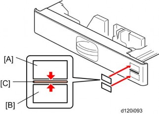
Attach the appropriate paper tray number decal [A] and paper size decal [B] to the line [C] on each tray of the paper feed unit.
![]()
The paper tray number and size sheet is in the accessory box of the main machine.
Lock the caster stoppers for the front two casters under the paper feed unit.
Load paper into the paper feed unit.
Turn on the main power switch of the machine.
Check the paper feed unit operation and copy quality.
Installation
Check the quantity and condition of the accessories against the following list.
No. | Description | Q'ty |
1 | Screw (M4x10) | 2 |
2 | Screw with Spring washer (M4x10) | 1 |
3 | Securing bracket | 2 |

![]()
Unplug the machine power cord before starting the following procedure.
The handles of the main machine for lifting must be inserted inside the machine and locked, unless these handles are used for the installation or relocation of the main machine.
You need two or more persons to lift the copier. The copier is highly unstable when lifted by one person, and may cause human injury or property damage.

Remove the strips of tape.

Grasp the handle [A] and grips [B] of the machine.
Lift the copier and install it on the LCT [C].
![]()
You need two or more persons to lift the copier.
![]()

Hold the handle [A] and grips [B] of the machine when you lift and move the machine.
Remove trays 1 and 2 of the machine.
Fasten the Spring Washer Screw [A].
Reinstall all trays.
Attach the securing brackets [B] ![]() x 1 each; M4x10).
x 1 each; M4x10).

Installation
Attach the appropriate paper tray number decal [A] and paper size decal [B] to the line [C] on the tray of the LCT.
![]()
The paper tray number and size sheet is in the accessory box of the main machine.
Lock the caster stoppers for the front two casters under the paper feed unit.
Load paper into the LCT.
Turn on the main power switch of the machine.
Check the LCT operation and copy quality.
Check the quantity and condition of the components against the following list.
No. | Description | Q'ty |
1 | Front Bracket | 1 |
2 | Rear Bracket | 1 |
3 | Stud Screw | 4 |
4 | Joint Pin | 2 |
5 | LCT | 1 |

![]()
Unplug the main machine power cord before starting the following procedure.
![]()
Installation
The Paper Tray Unit (D580) or LCT 2000-sheet (D581) must be installed before installing this 1200-sheet LCT.

Unpack the LCT and remove the tapes.
Remove the stand covers [A].
Release the locks [B] of the front and rear caster stands.
Remove the caster stands [C].

Remove the paper path cover [A], connector cover [B] and six hole covers [C].

Insert the joint pins [A].
Attach the front [B] and rear brackets [C]. ![]() x2 each)
x2 each)

Pull out the front and rear rails [A], and then hang them on each bracket [B].
Connect the LCT cable [C] to the main machine.
Slide the LCT [D] into the main machine.
Make sure that the front and rear sides of the LCT are closely attached to the main machine.
Installation
Check the quantity and condition of the accessories against the following list.
No. | Description | Q'ty |
1 | ARDF | 1 |
2 | Attention Decal Sheet – Top Cover | 1 |
3 | Stamp | 1 |
4 | Knob Screw | 2 |
5 | Stud Screw | 2 |
6 | Platen Sheet | 1 |

![]()
Remove the all tapes and shipping retainers.

Insert the two stud screws [A] on the top of the machine.
Mount the ARDF [A] by aligning the screw keyholes [B] of the ARDF support plate over the stud screws.
Slide the ARDF toward the front of the machine.
Secure the ARDF with the two knob screws [C].
Connect the I/F cable [D] to the machine.

Installation
Remove two screws [A] from the bottom of the ARDF.
Remove all tapes on the ARDF.

Place the platen sheet [A] on the exposure glass.
Align the rear left corner (of the platen sheet) with the corner [B] on the exposure glass.
Close the ARDF.
Open the ARDF and check that the platen sheet is correctly attached.

Open the ARDF cover [A].
Open the feed-in guide plate [B] and feed-out guide plate [C].
Install the stamp [D] into the ARDF.
Close two guide plates [C] [B].
Close the ARDF cover [A].

Attach the decal [A] to the top cover as shown. Choose the language you want.
Plug in and turn on the main power switch of the machine, and then check the ARDF operation.
Make a full size copy. Check that the registrations (side-to-side and leading edge) and image skew are correct. If they are not, adjust the registrations and image skew referring to the "Copy Adjustments" in the section of the "Replacements and Adjustments".
Installation
Check the quantity and condition of the components against the following list.
No. | Description | Q’ty |
1 | 1 Bin Tray Unit | 1 |
2 | End-fence | 1 |
3 | Tray Support Bar | 1 |
4 | Screws (M3 x 16) | 2 |
5 | Screws (M3 x 8) | 1 |
6 | Harness Cover | 1 |
7 | Tray | 1 |

![]()
If the bridge unit (D634) or side tray (D635) has already been installed in the machine, remove it before installing 1-bin tray unit (D632). This will make it easier for you to do the following procedure.
Remove all tapes.
Open the right door of the machine.
Remove the front right cover ![]() p.4-6).
p.4-6).
Remove the paper exit cover ![]() p.4-8).
p.4-8).
![]()
Keep the screw removed in step 4 for step 5.
Install the 1 bin tray unit [A] ( x 1, x 1 [This screw was removed in step 4]).

Attach the tray support bar [A] to the tray [B] as shown, and then attach the end-fence [C].

Installation
Install the tray [A] with the tray support bar in the machine (M3 x 16: ![]() x 2).
x 2).
Connect the harness to the connector of the 1-bin tray unit ![]() x 1).
x 1).
Attach the harness cover [A] ( x 1; M3 x 8).
Reinstall the front right cover on the machine, and then close the right door of the machine.
Turn on the main power switch of the machine.
Check the 1-bin tray unit operation.
Check the quantity and condition of the components against the following list.
No. | Description | Q’ty |
1 | Bridge Unit | 1 |
2 | Frame Cover | 1 |
3 | Knob Screw | 1 |
4 | Long Knob Screw | 1 |
5 | Holder Bracket Cover | 1 |
6 | Guide | 2 |

![]()
Unplug the copier power cord before starting the following procedure.
![]()
Installation
If you will install the 1-bin tray (D632) on the machine, install the 1-bin tray first before installing the bridge unit (D634). This makes it easy to do the following procedure.

If you will install the finisher unit (D588, D636 or D637) on the machine, install it after installing the bridge unit (D634).
Remove all tapes.
If the sensor feeler [A] is out, fold it into the machine.
Open the right door of the machine.
Remove the upper inner tray [A].
Remove the front right cover [B] ![]() x 1).
x 1).
Remove the connector cover [C] ![]() x 1).
x 1).

Attach the two guides [A] to the cutouts [B] in the inner tray.

Place the lower hook of the guide in the cutout of the paper exit.
Attach the guide as shown until the two side hooks hold the paper exit.
Press the guide.
Press down the guide as shown.

Installation
Install the bridge unit [A] in the machine.

Secure the bridge unit with the long knob screw [A] and knob screw [B].
Attach the frame cover [C].
Reinstall the front right cover on the machine, and then close the right door of the machine.
![]()
Open the bridge unit cover [D] when installing the front right cover. Otherwise, you cannot reinstall it.
Install the optional finisher (refer to the finisher installation procedure).
![]()

Holder bracket [E] is used in the installation procedure of the finisher (D588, D636 or D637). Do not install it at this time.
Pull out the extension tray [A] only if the 1000-sheet finisher (D588) will be installed on the main machine.
Turn on the main power switch of the machine.
Check the bridge unit operation.
Installation
Check the quantity and condition of the accessories against the following list.
No. | Description | Q'ty |
1 | Rear joint bracket | 1 |
2 | Front joint bracket | 1 |
3 | Ground (earth) plate | 1 |
4 | Tapping screws - M4 x14 | 4 |
5 | Tapping screws - M3 x 8 | 1 |
6 | Tapping screws - M3 x 6 | 6 |
7 | Upper output tray | 1 |
8 | Support Tray | 1 |
9 | Lower output tray (D637 only) | 1 |
10 | Cushion (with double-sided tape) | 1 |
11 | Small Ground (earth) plate | 2 |
![]()
Unplug the main machine power cord before starting the following procedure. If this finisher is installed on this machine, the following options must be installed before installing this finisher.
Bridge Unit (D634)
Paper Feed Unit (D580) or LCIT (D581)

Unpack the finisher and remove all tapes and packing materials from the finisher.

Open the front door, and then remove all tapes and packing materials from the inside of the finisher.
Installation
Pull out the jogger unit [A], and then remove all tapes and retainers.

Attach the cushion [A] to the finisher.
![]()
Make sure that the cushion is placed within 0 to 1 mm from the edge of the cover.
Install the ground plate [B] on the finisher ![]() x 2; M3 x 6).
x 2; M3 x 6).
Install the small ground plates [C] on the ![]() x 2; M3 x 6 each).
x 2; M3 x 6 each).

Attach the rear joint bracket [A] ![]() x 2; M4 x 14).
x 2; M4 x 14).
Attach the front joint bracket [B] and the holder bracket [C] ![]() x 2; M4 x 14).
x 2; M4 x 14).
![]()
Holder bracket [C] must be placed outside the front joint bracket [B]. This bracket is provided with the Bridge Unit (D634).

Pull the lock lever [A] ![]() x 1).
x 1).
Slowly push the finisher to the left side of the machine, keeping its front door open until the brackets [B] [C] go into their slots.
Push the lock lever [A], and then secure it ![]() x 1).
x 1).
Close the front door of the finisher.
Connect the finisher connector [D] to the machine.

Installation
Install the upper output tray [A] ![]() x 1; M3 x 8).
x 1; M3 x 8).
Only for D637, install the lower output tray [B].
Turn on the main power switch of the machine.
Check the finisher operation.

If a stacking problem occurs several times on the upper output tray [A], put the support tray [B] on the tray as shown.
![]()
Keep this tray in the manual pocket if this tray does not need to be installed.
The Punch Unit D570 can be installed in the 3000/2000-Sheet (Booklet) Finisher D636/D637.
Check the quantity and condition of the components against the following list.
No. | Description | Q'ty |
1 | Punch-out Waste Unit | 1 |
2 | Slide Drive Unit | 1 |
3 | Punch Waste Hopper | 1 |
4 | Wire harness: short-circuit | 1 |
5 | Screws (M3 x 6) | 5 |
6 | Side-to-Side Detection Unit | 1 |
7 | Punching Unit | 1 |

![]()
Installation
Unplug the main machine power cord before starting the following procedure. If the 2000/3000-sheet booklet finisher has been installed, disconnect it and pull it away from the machine.
Remove all tapes and shipping retainers.

If the finisher is connected to the copier, disconnect the power connector [A] and separate the finisher from the copier.
Remove the rear cover [B] ![]() x 2) and open the front door.
x 2) and open the front door.
![]()
At the base of the back cover, be sure to disconnect the tabs that fasten the cover to the frame.
Remove the guide plate [C] ![]() x 2).
x 2).
Remove the shipping retainer [A] ( x 2) from the punch unit.
Move the punch unit [A] along its rails into the finisher. Make sure that the pin engages correctly at the front and rear.
Connect the cables [B] of the finisher to the connectors (CN601 and CN602) on the punch unit board ![]() x 2,
x 2, ![]() x 1).
x 1).
The cables [B] are coiled and attached to the PCB.
Installation
Attach the slide drive unit [A] to the finisher and connect it to the punch unit ![]() x 2,
x 2, ![]() x 1). Push in the slide drive unit at
x 1). Push in the slide drive unit at ![]() when you attach the screw
when you attach the screw ![]() .
.
Make sure that the punch unit moves freely and is not blocked by the screws.

Put the side-to-side detection unit [A] in the machine. Make sure that the two pins are engaged correctly at the front.
Make sure that the side-to-side detection unit moves smoothly on its rails. If it does not, make sure that the rails are aligned with their grooves.
Attach the side-to-side detection unit and connect it at the rear ![]() x 2,
x 2, ![]() x 1,
x 1, ![]() x 1).
x 1).
Pull the short connector out of the connector [B], then connect the cable of the finisher ![]() x 1).
x 1).
![]()
This is the 3-pin connector.

Connect "Wire harness: short-circuit" [A] to the CN110 connector.

At the front, use a pair of wire cutters to remove the part [A] of the cover.
Install the punch-waste transport unit [B] in the finisher.
Make sure that the punch-waste transport unit moves smoothly on its rails. If it does not, make sure that the rails are aligned with the grooves.
Remove the short connector from the connector [C].
![]()
This is the 4-pin connector.
Installation
Connect the cable to connector [C] and attach the punch-waste transport unit ![]() x 1,
x 1, ![]() x 1,
x 1, ![]() x 1).
x 1).

Set the hopper [A] in its holder.
Reassemble the finisher, and then install it on the main machine.
Connect the power cord to the outlet, and then turn the main power switch on.
Check the punch unit operation.

Install screws [1] ![]() x 2) on the top cover as shown.
x 2) on the top cover as shown.
Position the platen cover bracket [2] on the heads of the stud screws, and slide the platen cover [3] to the left.
Installation
Check the quantity and condition of the accessories against the following list.
No. | Description | Q'ty | For this model |
1 | Grounding Plate | 1 | Yes |
2 | Rear Joint Bracket | 1 | Not used |
3 | Front Joint Bracket | 1 | Yes |
4 | Rear Joint Bracket | 1 | Yes |
5 | Copy Tray | 1 | Yes |
6 | Screw - M3 x 8 | 1 | Yes |
7 | Screw - M4 x 13 | 4 | Yes |
8 | Knob Screw - M3 x 8 | 1 | Yes |
9 | Knob Screw - M4 x 10 | 1 | Yes |
10 | Screw - M4 x 25 | 3 | Not used |
11 | Staple Position Decal | 1 | Yes |

![]()
Unplug the main machine power cord before starting the following procedure.
If this finisher is installed, the Bridge Unit (D634) and Paper Feed Unit (D580) or LCT (D581) must be installed before installing this finisher.


Unpack the finisher and remove the tapes.
![]()
Be sure to keep screw [A]. It will be needed to secure the grounding plate in step 3.

Installation
Install the rear joint bracket [A] ![]() x 2; M4 x 13) and front joint bracket [B]
x 2; M4 x 13) and front joint bracket [B] ![]() x 2; M4 x 13).
x 2; M4 x 13).
![]()
Holder bracket [C] must be placed outside the front joint bracket [B]. This bracket is provided with the Bridge Unit (D634).
Install the grounding plate [A] on the finisher ( x 2; M3 x 8)
3.
![]()
Use the screw removed in step 1 and the screw from the accessory box.
Open the front door [B]. Then pull the locking lever [C].
Align the finisher on the joint brackets, and lock it in place by pushing the locking lever.
Secure the locking lever ![]() x 1; knob M3 x 8) and close the front door.
x 1; knob M3 x 8) and close the front door.
Install the copy tray [D] ![]() x 1; knob M4 x 10).
x 1; knob M4 x 10).
Connect the finisher cable [E] to the main machine as shown above.

Attach the staple position decal [A] to the ARDF as shown.
Turn on the main power switch and check the finisher operation.
Installation
Check the quantity and condition of the accessories against the following list.
No. | Description | Q’ty |
1 | Side Tray Unit | 1 |
2 | Sub Output Tray | 1 |
3 | Main Output Tray | 1 |
4 | Screw | 1 |
5 | Knob Screw | 1 |
6 | Frame Cover | 1 |
7 | Holder Bracket Cover | 1 |
8 | Guide | 1 |

![]()
Turn off the main switch of the copier and unplug the power cord before you start the installation procedure.
![]()

If you will install the 1-bin tray (D632) on the machine, install the 1-bin tray first before installing the side tray (D635). This makes it easier to do the following procedure.
Remove all tapes.
If the sensor feeler [A] is out, fold it into the machine.
Open the right door of the machine.

Remove the inner tray [A].
Remove the front right cover [B] ![]() x 1).
x 1).
Remove the connector cover [C] ![]() x 1).
x 1).

Installation
Attach the two guides [A] to the cutouts [B] in the inner tray.
Place the lower hook of the guide in the cutout of the paper exit.
Attach the guide as shown until the two side hooks hold the paper exit.
Press the guide.
Press down the guide as shown.

Attach the main output tray [A] and sub output tray [B] to the side tray unit.

Install the side tray unit [A] in the machine.

Open the side tray cover [A].
Secure the side tray unit with the knob screw [B].
Attach the frame cover [C].
Reinstall the front right cover on the machine, and then close the right door of the machine.
![]()
Open the side tray cover [A] when installing the front right cover. Otherwise, you cannot reinstall it.
Install the holder bracket [D] ![]() x 1).
x 1).
Turn on the main power switch of the machine.
Installation
Check the side tray operation.
Check the quantity and condition of the components against the following list.
No. | Description | Q’ty |
1 | Shift Tray Unit | 1 |
2 | Paper Guide - Small | 2 |
3 | Connector Cover | 1 |

![]()
Unplug the copier power cord before starting the following procedure.
Remove all tapes.
Remove the standard tray [A].
Installation
Remove the inner cover [B] ![]() x 1).
x 1).

Install the small paper guides [A].

Attach the connector cover [A] to the shift tray unit [B].
Install the shift tray unit [B] in the machine.
Push down the left edge [C] of the shift tray.
Turn on the main power switch of the machine.
Check the shift tray unit operation.
Hold the key counter plate nuts [1] on the inside of the key counter bracket [2] and insert the key counter holder [3].
Secure the key counter holder to the bracket ![]() x 2).
x 2).
Install the key counter cover [4] ![]() x 2).
x 2).
Rear cover [5] ![]() x 5)
x 5)

Installation
Cut off the part [6] of the rear cover.
Connect the harness to CN211 [7] on the IOB ( x 3).
6.

Peel off the double-sided tape on the key counter bracket and attach the key counter to the scanner right cover [8].
Reassemble the machine.

Rear cover [1] ![]() x 6)
x 6)

Install the key counter interface board in the location [2] ![]() x 4).
x 4).
Connect the harness to CN3 on the key counter interface board.
Connect the other terminal of the harness to CN214 [3] on the IOB ![]() x 3).
x 3).

Installation
Cut off the part [4] of the rear cover.

Connect the harness from the counter device to CN4 on the key counter interface board and clamp it with three clamps [5].
Reassemble the machine.

Remove trays 1 and 2 from the machine.
Connect the connector [1] of the heater to the connector [2] of the main machine.
Install the heater [3] inside the machine ![]() x 1).
x 1).
Remove the connector cover [4] ( x 1).
4.
< Previous page: Part 1 | You are viewing page: Part 2 | Next page: Part 3 >